Great thread! I have gone through the entire thread and learnt a great deal.
One thing that has not been discussed is the impact of the fuse resistance on the power supply reservoir capacitance.
In this thread we discussed power supply reservoir size. The size affects a number of things: the ability to deliver the current on demand without sagging the rails by too much; the ability to reduce ripples in terms of "line regulation" (PSSR) and "load regulation" (low impedance), the later of which requires low impedance decoupling right at the power device pins.
The problem is that the power rail fuse is usually placed after all the reservoir caps and before the local decoupling / bypass capacitor, usually with a 100uF-220uF electrolytic. A capacitor of this size will have relatively high ESR so the impedance is not low. I was shock when reading Bob Cordell 's book about fuse distortion:
"The cold resistance of a 2-A 3AG fuse was measured to be 78 mΩ, while its resistance when passing 2-A DC was 113 mΩ. This represents a 45% increase in fuse resistance."
So the power devices will never see a low impedance from the power supply. The result is higher ripples on music signals. We could throw in large reservoir capaictance in hope that it will deliver, but if we don't first solve the problem of fuse resistance then our efforts of increasing the reservoir capactance can be nullified.
So the questions are: if we need to increase the local decoupling / bypass capacitance after the fuse to reduce the impedance seen by the power devices, what value of local decoupling capacitance can produce a low enough supply impedance? What is the maximum local decoupling capacitance allowed without the danger of burning the fuse when powered on, considering using a softstart circuit? When the fuse is burnt due to over current during music playing is there any chance that the energy store in the large local decoupling capacitors causes further damage to the amplifier / speaker therefore defeating the purpose of the fuse?
Regards,
Bill
Last edited:
Yeah, fuse goes before the primary---among other things that's required to protect against magnetostriction induced insulation failures in the trafo. At low blow ratings (tens of milliamps) the fuse resistance gets fairly high (tens of ohms, IIRC), resulting in potentially lower rail voltage depending on how the load beats against the mains. Doesn't normally come up but I have seen the issue in some of the little amps I've built.
Instead of worrying about overcurrent detection and relays and such a simpler protection mechanism is to size the rails for the voltage that's actually needed. For example, the poll over the multiway forum shows 75% of folks need 5V or less out of their amps. That means you can potentially run a perfectly satisfactory amp off a 6V trafo, leading to something like 12W of dissipation in an 8 ohm driver in the event of a short to the rails. Most drivers are rated for continuous levels significantly higher than that...
Instead of worrying about overcurrent detection and relays and such a simpler protection mechanism is to size the rails for the voltage that's actually needed. For example, the poll over the multiway forum shows 75% of folks need 5V or less out of their amps. That means you can potentially run a perfectly satisfactory amp off a 6V trafo, leading to something like 12W of dissipation in an 8 ohm driver in the event of a short to the rails. Most drivers are rated for continuous levels significantly higher than that...
Last edited:
So, a fuse in the speaker line is doing a brilliant job of adding horrendously non-linear resistance in series with the speaker impedance. Well past the ability of any feedback to do anything about it ..."The cold resistance of a 2-A 3AG fuse was measured to be 78 mΩ, while its resistance when passing 2-A DC was 113 mΩ. This represents a 45% increase in fuse resistance."
And, some people sneer at the concept that fiddling with fuses can make a difference to the sound ...
")
To "blow" a fuse you need a certain amount of energy, and at very low currents that will require to waste a few volts and it depends on the application if this an issue or not.
Those (mostly lousy built) little 5mm glassfuse-holders can make trouble in applications with high peak currents, contact resistance stability is not exactly what one would like it to be...
Those (mostly lousy built) little 5mm glassfuse-holders can make trouble in applications with high peak currents, contact resistance stability is not exactly what one would like it to be...
Fuses are nonlinear but so are the caps and diodes etc. (not to mention the thermal coefficient of the copper in the transformer). There is a fuse in the mains (the most user accessible one) in series with at least 200 feet of 12 AWG wire at 150 mOhms not to mention the drop from the pole and the internal resistance of the transformer up there. The question would be the peak difference in percentage from a perfect (if it were, its not) 120V AC source to load a the load changes from min to max in the amplifier. How much does that fuse affect that voltage. Follow the same process for the DC supply fuse. And look at the change in the drop on the rectifiers as the current changes. Then add the time constants of the supply components (and that of the fuse resistance) and see how much impact it has.
A fuse in series with a speaker is a much bigger issue and feedback around the fuse works. Or scale the supply fuses to do the same protection, it worked for the Spectral amps, actually better since the fuses were preheated by the bias current.
A fuse in series with a speaker is a much bigger issue and feedback around the fuse works. Or scale the supply fuses to do the same protection, it worked for the Spectral amps, actually better since the fuses were preheated by the bias current.
So, a fuse in the speaker line is doing a brilliant job of adding horrendously non-linear resistance in series with the speaker impedance. Well past the ability of any feedback to do anything about it ...
And, some people sneer at the concept that fiddling with fuses can make a difference to the sound ...
I just came up with a new type of fuse for those fiddlers, a "water cooled fuse" made of zero tempco wire. As long as the wire is surrounded by water it will be a stable resistance, when the wire heats up to the point that a mantle of steam developes it will isolate the wire from the cooling water and the wire would melt.
Last edited:
Assume that the fuse resistance is 100mR when 5A current is passing through it will develop a ripple of 500mV.
The tens of microfarad reservoir capacitance we put in are not just for reducing the mains ripples and noise but also to reduce the power supply impedance seen from the power devices to a few mini ohms from above 1kHz to 100kHz, reducing ripples when current is drawn from the power supply. The fuse resistance of 100mR defeats this purpose.
The tens of microfarad reservoir capacitance we put in are not just for reducing the mains ripples and noise but also to reduce the power supply impedance seen from the power devices to a few mini ohms from above 1kHz to 100kHz, reducing ripples when current is drawn from the power supply. The fuse resistance of 100mR defeats this purpose.
What about the (admittedly small) chance of the amp going bad in such a way that the feedback path gets a fat DC, etc, applied?A fuse in series with a speaker is a much bigger issue and feedback around the fuse works. Or scale the supply fuses to do the same protection, it worked for the Spectral amps, actually better since the fuses were preheated by the bias current.
But if the voicecoil still sees an undistorted voltage drive I can't see this being as major a problem ...In my view, the biggest issue with tempco is the tempco of voicecoils, especially when they are part of a active speaker filter
Here are some graphs to illustrate.
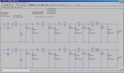
Suppose we have a power amplifier supply using CLRCLRC of 10000uF + 10uH + 0.1R + 10000uF + 10uH + 0.1R + 20000uF + (local) 220uF.
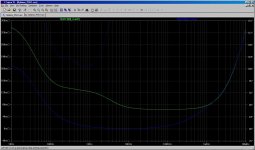
The graphs are as shown. The rising impedance above 10kHz is due to the wire inductance.
The only difference between the two circuits is that one assumes 130mR fuse resistance and the other one is basically 0R.
The green graph is the one with 130mR fuse resistance and the blue graph is without the fuse. See the very big differences.
Suppose we have a power amplifier supply using CLRCLRC of 10000uF + 10uH + 0.1R + 10000uF + 10uH + 0.1R + 20000uF + (local) 220uF.
The graphs are as shown. The rising impedance above 10kHz is due to the wire inductance.
The only difference between the two circuits is that one assumes 130mR fuse resistance and the other one is basically 0R.
The green graph is the one with 130mR fuse resistance and the blue graph is without the fuse. See the very big differences.
Attachments
Did you ever thinck of the impact the tempco of the voicecoil has on the Q in a 2 - 6th order filter?But if the voicecoil still sees an undistorted voltage drive I can't see this being as major a problem ...
Thinck again please
Last edited:
Get a good milliOhmmeter (HP 4328A for example) and start measuring real world parts. 100 milliOhms for a source Z above 10 KHz will prove to be quite difficult to get even a few inches from the caps. Jneutron has posted some pictures of the kinds of hoops you must jump through to get low Z at high frequencies.
If your amplifier is sensitive to a power supply source Z of 100 milliOhms you might hear a major improvement in it if you figure out why and address it.
If your amplifier is sensitive to a power supply source Z of 100 milliOhms you might hear a major improvement in it if you figure out why and address it.
Hmmm, looking around this seems to get quite complicated fast, obviously there will be frequency response variations but that sort of thing, for me at least, is very minor -- I worry about non-linear distortion, a far, far bigger enemy. I note this thread on the matter, but won't attempt to digest it at the moment ...Did you ever thinck of the impact the tempco of the voicecoil has on the Q in a 2 - 6th order filter?
Which is why so many amplifiers don't cut it, when you put the pressure on. 20 years ago it was pretty disasterous, you could easily hear even the most gung-ho amplifiers starting to collapse in SQ at relatively low volumes, more recently things appear to have improved somewhat.100 milliOhms for a source Z above 10 KHz will prove to be quite difficult to get even a few inches from the caps. Jneutron has posted some pictures of the kinds of hoops you must jump through to get low Z at high frequencies.
If your amplifier is sensitive to a power supply source Z of 100 milliOhms you might hear a major improvement in it if you figure out why and address it.
Low impedances are possible, you just have to take it seriously, not just treat it as an afterthought ..
To add some perspective, for those who may be interested, the first reasonable cost commercial amp that really made me snap to attention was hearing a demo of Greg Ball's Eidetic, about 20 years ago. He was known on diyAudio as amplifierguru, but parted ways some time ago -- his amp was no looker, relatively tiny, but it had balls (no pun intended, ) ! I heard it in a big space, driving a pair of absolutely rubbish looking, badly knocked around speakers, and it created a "big" sound with no trouble at all.
It showed me that there were a few people out there who knew what they were doing, but unfortunately they were few and far between ...
) ! I heard it in a big space, driving a pair of absolutely rubbish looking, badly knocked around speakers, and it created a "big" sound with no trouble at all.It showed me that there were a few people out there who knew what they were doing, but unfortunately they were few and far between ...
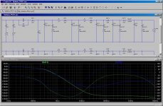
Put the fuse way farther upstream. It should never be placed there, in a real system.
By the way, wires 3, 4, 6, and 7 have 10 uH instead of 10 nH.
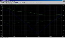
The 10uH is by design. It makes basically no difference in impedance seen at the power device pins because the low impedance is provided by the last stage two large reservoir capacitors, however, with the two small chokes it will result in substantially improved high frequency PSSR of the power supply.
See the PSSR graph attached.
In all of the power amp circuits I have seen, the rail fuse is placed after the reservoir capacitors. I think this is for two reasons: 1) The inrush current is very large and can blow the fuse when the amp is turned on if the fuse is before the capacitors because the capacitors before being charged will work as a short to the ground and this inrush current will go through the fuse and burn the fuse. Placing the fuse after the reservoir capacitors will not have the same problem. 2) Perhaps after the fuse is burnt in a fault condition we don't want large stored energy on the big capacitors on the circuit board which may continue to cause damage to possibly the speakers. If the fuse is after all the big capacitors then after the fuse is burnt (power rail open) there is no stored energy to cause any further damage. I am not sure if the second reason is valid or not.
Attachments
Last edited:
For the above second reason, perhaps it works this way - if the speaker terminals are shorted, the fuse will be burnt and this protects the output transistors. If there is still large capacitance after the fuse then a considerable amount of current from the stored energy of the capacitors will still go through the output transistors, which may cause damage.
I am not sure if this can be true or not. It is only a guess.
I am not sure if this can be true or not. It is only a guess.
- Status
- This old topic is closed. If you want to reopen this topic, contact a moderator using the "Report Post" button.
- Home
- Amplifiers
- Power Supplies
- Power Supply Resevoir Size