The diagram in your post 1135 was certainly fiction, but not much to do with science, and it was not unanswered: I pointed out the flaws in the bottom of post 1138.OnAudio said:Later there was a science fiction piece that went un answered
The misunderstandings in your post 785 might not have been answered, though.
Why drag them up now, when they are best forgotten?
The diagram in your post 1135 was certainly fiction, but not much to do with science, and it was not unanswered: I pointed out the flaws in the bottom of post 1138.
The misunderstandings in your post 785 might not have been answered, though.
Why drag them up now, when they are best forgotten?
Thank you DF96. A very simple circuit would be a passive first order low pass filter. What happens when you increase the load resistance
") ?
?Not certain about relevance, but it would depend on whether it was CR or LR.OnAudio said:A very simple circuit would be a passive first order low pass filter. What happens when you increase the load resistance ?
For CR low pass increasing the load resistance increases attenuation and raises corner frequency.
For LR low pass increasing the load resistance does not affect attenuation and lowers corner frequency. So what?
Not certain about relevance
For LR low pass increasing the load resistance does not affect attenuation and lowers corner frequency. So what?
Thank you DF96.
Does this in any way affect transient response ?Just to clarify, by 'increasing the load resistance' I actually meant 'applying a greater load' i.e. reducing the numerical value of the load resistance. Sorry for the confusion.
My point is that CR and LR filters behave in opposite ways as the R value changes. I seem to recall confusion on this might have been the original issue.
My point is that CR and LR filters behave in opposite ways as the R value changes. I seem to recall confusion on this might have been the original issue.
In this case, it would be a lot more reliable to type the post number.Did you mean to point to post1501? Twice?
Here's the parameters:
Intra-thread links to attachments works fine,
Inter-thread links to attachments work fine,
intra-forum/inter-thread links (between two threads) links to posts work fine,
but intra-thread links (within same thread) to posts are hit or miss.
I also got 1501 twice.
For a large project, here's a workaround:
Discussion, simulation and testing on the big "main" thread, versus soldering and shopping on the little "build" thread.
A build thread is a "summary" concept and post 1 is re-edited in reaction to new questions in order to create more effective documentation. To avoid intra-thread links (that can miss the target), the links must refer to a different thread, which is the longer main/development thread. A build thread (a summary) can be started as a collection of notes and links all in post 1 of a new thread (post 1 has forever edit), and that can be reorganized into something cohesive after the task of reading through and making notes on a long thread is completed. The majority of build thread content is actually posted on the main thread, and, in that case, the links work.
----
Meanwhile, back on topic. Do amplifier topologies vary widely on power supply requirements, or is that one unusual? The low bass power is generous and audio resolution is seemly with just 160va and 4400uF per rail for my circlo monobloc. However, my other amplifiers seem to need more voltage, double the current and triple the capacitance before achieving a similar performance. Why?
A simple answer would be the the PSRR of the amplifier circuit, the ability to ignore the fluctuations of the voltage rails, especially at high frequencies. Real supplies with minimal specs inject a lot of rubbish into the amp, and there are dramatic differences in the way the different circuit configurations react. So, if you're not sure, build a Mack truck of a power supply ...Meanwhile, back on topic. Do amplifier topologies vary widely on power supply requirements, or is that one unusual? The low bass power is generous and audio resolution is seemly with just 160va and 4400uF per rail for my circlo monobloc. However, my other amplifiers seem to need more voltage, double the current and triple the capacitance before achieving a similar performance. Why?
Frank
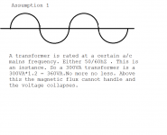
What would be the instantaneous max VA for a 300VA transformer ?
how hot can you allow your traffo to become?
instantaneous could be 100ms or 10ms or 1ms or 100us or 10us or 1us or more accurately an instantaneous moment that has no measurable time period. It is an instant.
If the period is very short there is little time for any heating to occur.
Then there will be no measurable increase in temperature.
For very short term overloads, I'd suggest 10times VA is acceptable. Transformers are very tolerant of short term overload.
If the period is very short there is little time for any heating to occur.
Then there will be no measurable increase in temperature.
For very short term overloads, I'd suggest 10times VA is acceptable. Transformers are very tolerant of short term overload.
Apart from PSRR the critical feature (for reservoir cap size, the topic of this thread) is voltage drop in the output stage (including any emitter resistors), especially when compared with the difference between off-load rail volts and required peak output volts. If you increase the voltage drop then you have to increase the cap size so the supply voltage droop under load is reduced.danielwritesbac said:Do amplifier topologies vary widely on power supply requirements,
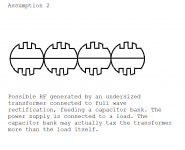
Though, piling on more capacitors, of the right type and in the right area is highly productive. Because this markedly reduces, shall we call it, micro fluctuations ... higher frequency disturbances of the voltage rails, the sort of thing that loves jumping around inside a circuit via all the parasitic capacitances that are part of real components. If you're into "micro detail" in your sound then this just may be part of the answer ...I think the second attachment of post 1532 is showing a futile attempt of continuing to pile on more capacitors to the too small transformer. That is counterproductive. Some of Tom's spreadsheets listed those conditions as impossible, invalid, or a negative number.
Frank
Originally Posted by danielwritesbac
I think the second attachment of post 1532 is showing a futile attempt of continuing to pile on more capacitors to the too small transformer. That is counterproductive. Some of Tom's spreadsheets listed those conditions as impossible, invalid, or a negative number.
Though, piling on more capacitors, of the right type and in the right area is highly productive. Because this markedly reduces, shall we call it, micro fluctuations ... higher frequency disturbances of the voltage rails, the sort of thing that loves jumping around inside a circuit via all the parasitic capacitances that are part of real components. If you're into "micro detail" in your sound then this just may be part of the answer ...
Frank
And in my spreadsheet, the capacitances are what would have been _required_, in order to have no possibility of even a tiny bit of clipping. It had nothing to do with adding extra (or too much) capacitance to an already-OK situation. It only meant that the cases being considered were either impossibly underpowered, or almost so.
Though, piling on more capacitors, of the right type and in the right area is highly productive.
I was looking at some caps I pulled out of a poweramp I'm currently modding yesterday on my LCR meter and took a bit more trouble than normal to understand how the impedance was changing with frequency. They're 10,000uF/50V a fairly typical value for a mid-range amp.
What I saw was though the capacitance was close to the sticker value at 50Hz it fell at higher measurement frequencies. Here are the values I jotted down in my notebook:
50Hz 9,535uF
1kHz 8,035uF
10kHz 1,530uF
20kHz 495uF
Anyone else come across this? I tried a couple of other brands (Rubycon, Elna), similar results. The capacitance is down to 5% of its marked value at 20kHz, seemingly due to internal inductance which, in turn varies with frequency. I calculate about 0.5uH @ 1kHz down to 120nH at 20kHz.
- Status
- This old topic is closed. If you want to reopen this topic, contact a moderator using the "Report Post" button.
- Home
- Amplifiers
- Power Supplies
- Power Supply Resevoir Size