i don't think there is a maximum capacitance, over which there is deterioration of the sound produced. The more capacitance there is, the more stable is the power supply and the closer it gets to a true constant voltage power supply
To put it bluntly, i think it is bogus to claim that there can be too much capacitance.
unless i am missing something quite fundamental
To put it bluntly, i think it is bogus to claim that there can be too much capacitance.
unless i am missing something quite fundamental
Tom you must be itching to double the cap values for better bass punch. On the other hand Mooly would want to half the cap values to cater for "speed" and clarity. This is now open for discussion and throwing a couple of punches are allowed, we want to get to a happy medium and a rule of thumb power supply design that sports a wide range of sonic experiences.
Nico the solution for this dilema lies in stronger, lower Zsec transformer, ie. 400 VA (more amps to charge cap bank faster). Also 4 ohm performance would be much better than with only 200 VA.
")
If the voltage gain stages run from a stabilized supply, the output stage will do fine with very small capacitors.
With the stabilized supply for the front-end the only way you will hear a difference is when running into clipping. When running into clipping the bigger caps will show more tilt in the square-wave.
" i think it is bogus to claim that there can be too much capacitance."
A 1A rectifier with a 1000µF cap and a 1A load will have roughly 1A peak charging current (ignoring the transformer DCR for a minute). Increasing the cap to 100,000µF will increase the peak charging current to 100A and blow the rectifier to silicon nirvana (and let the magic smoke out).
"the cycle of charge/discharge is longer for larger caps "
And a 1 Farad cap will deliver 1A for 1 second, so what?
Did anyone not understand the material in post #59?
Tsiros, don't speculate give a number that you feel is adequate. Tom has provided many formulas so have a look see if you agree. Would the ripple be acceptable with 2 x 4700uF.
Qusp you are right about the time to charge the bigger caps because this is directly related to the transformer impedance, but the "Cat" has improvised by allowing 66% more guts. (actually 100% but he must argue his point) djk is also correct especially at turning the power on you could fry the rectifier if it exceeds the rectifier safe operating current. DJK I do not think many people follow links, maybe copy and paste what you are saying it will be readily available.
Qusp you are right about the time to charge the bigger caps because this is directly related to the transformer impedance, but the "Cat" has improvised by allowing 66% more guts. (actually 100% but he must argue his point) djk is also correct especially at turning the power on you could fry the rectifier if it exceeds the rectifier safe operating current. DJK I do not think many people follow links, maybe copy and paste what you are saying it will be readily available.
Last edited:
DJK I acually support you so does Andrej and I take it you will be comfortable with the 4700 x 2 caps (maybe less). I have a feeling that Mooly would also look at only 4700 uF or there about (Lets hear your view Mooly) and Andrej's 400VA and Toms 10 x 470uF caps may just be perfect for this purpose. This really boils down to 1000uF per amp and 4 x watts = transformer VA (provided the front end is separate and smooth) Do we agree with 33uF and 330nF shunting the electrolytics, but is it really necessary if we have a bunch of 470 uF caps, can we not just shunt it with one 100nF.
Last edited:
There is a definite trend towards a big bank of smaller 1000uF caps rather than huge 10000uF caps. Seems like there is something there. If you search the Chip Amp forums, the ridiculous go for 20-30 1000uFs in parallel.
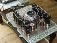
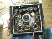
Personally I run a Class A 100W amp with 6 x 33000uF Computer Grade Dubilier Caps.
That's 12 caps for 2 x +/-48V. Running in dual MonoBlock.
I inherited this from my brother-in-law. It is a clone of a Pass Aleph 4.
Personally I run a Class A 100W amp with 6 x 33000uF Computer Grade Dubilier Caps.
That's 12 caps for 2 x +/-48V. Running in dual MonoBlock.
I inherited this from my brother-in-law. It is a clone of a Pass Aleph 4.
Attachments
Last edited:
Okay the rule of thumb indicates 2000uF/amp
Tell me more
"especially at turning the power on you could fry the rectifier if it exceeds the rectifier safe operating current"
Pehhaps I did not make the point correctly, the 100A peak is repetitive, it will occur every 8.3mS (10mS/50hz), it is not the initial turn-on surge.
"seems that 4700uF caps are not enough for 400W RMS for two channels or one channel"
The values for power supply capacitance can be realistically determined by a consideration of the numerical value of W C R where W is the line frequency (377 rad/sec), C is the power supply capacitance, and R is the load resistance. An WCR value of 10 yields about 10 per cent ripple (pk.-pk. ) and a value of 100 has about two percent. Below 10, the power supply will have serious problems and values of about 100 will achieve diminishing performance returns. The minimum value then, for each of the four power supply capacitors should be about 3,000uF and the maximum about 30,00OuF. Capacitances above this value may cause diode bridge failure due to turn-on surges and are not recommended.
(http://www.passdiy.com/pdf/a40.pdf)
3,300µF x2 for one channel at 8Ω with 60hz line (3,900µF for 50hz), double for 4Ω, double again for 2Ω.
Example: Crest CA9 has a tiered supply and 120,000µF total capacitance. This is 15,000µF per channel, per tier, the 10% ripple point.
Remember, stored energy increases with the square of the voltage, so a 3,300µF cap with 100V on it stores 4x the energy that a 3,300µF cap with 50V on it stores.
radian per second = W
f*2Pi=W
377 (60hz)
314(50hz)
Have a look at your own thumb mate, mine is patented.Tell me more
Have a look at your own thumb mate, mine is patented.
We work out to the same value for that situation
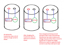
Okay djk firstly I have a comment, you will only draw the full current if you have depleated all the energy from the cap, the amount of current flow would be directly proportional to the difference in terminal voltage on the cap and peak voltage of the transformer. But I did say in the specification that we must assume 100% duty cycle and in that case you are correct.
So I take it you want to see 12 000uF per rail on our fictitious 100 watt amp to operate good at 4 ohm? That ties in with Andrej want 400 VA, Is this settled then:
For a 100 watt rms mono 8 ohm resistive load amp, we need a transformer that is 400VA (I think you are a bit nuts but if this is what works then so be it) followed by 12000uF/rail and our rule becomes 3 300 uF per amp. All happy? nobody wants to throw a punch at any of these clever dicks. In that case our rule stands.
Harrison if I may say so, nobody looked at your question - what I say may come as a surprise to you. Your logic is spot on, only the way you say it sounds a little fabricated.
Just keep in mind that a capacitor discharging does not do this in linear packets of energy. Each packet is slightly smaller than the previous due to a voltage drop. But you are correct. I do not understand your question though, what is there that you need solved
Just keep in mind that a capacitor discharging does not do this in linear packets of energy. Each packet is slightly smaller than the previous due to a voltage drop. But you are correct. I do not understand your question though, what is there that you need solved
Is there a reason for it standing on oven mittens?
Some people don't like unnecessary scratches on their furniture I guess. It takes less effort to protect stuff than repairing it afterwards.
Harrison if I may say so, nobody looked at your question - what I say may come as a surprise to you. Your logic is spot on, only the way you say it sounds a little fabricated.
Just keep in mind that a capacitor discharging does not do this in linear packets of energy. Each packet is slightly smaller than the previous due to a voltage drop. But you are correct. I do not understand your question though, what is there that you need solved
Show you grasp the logic by solving #70 and #71
- Status
- This old topic is closed. If you want to reopen this topic, contact a moderator using the "Report Post" button.
- Home
- Amplifiers
- Power Supplies
- Power Supply Resevoir Size