whoopee!
thanks Frank.
Symmetry's a good sign. Ooh, hyperbola. Air gap is a useful addition. First impression of hysteresis is not especially encouraging because of the need to specify a constant operating frequency. OK for approximations to mains transformers, but no good for audio transformers where frequency varies. Also, because it's a curve-fitting exercise, it's hard to estimate the error compared to the real thing. Worth ripping though. I'll look at how LTSPICE implements it and incorporate it if it's not too hard. It'll take some time though.
It would be very nice if I could get a copy of Chan's paper without joining Yahoo. Otherwise I'll have to wait until I go to the library to download it. If it is just a reworking of Hymowitz, it may not be worth using.
This paper:
http://www.onsemi.com/pub_link/Collateral/AN1679-D.PDF
was intended for modelling transformers in switch-mode power supplies. Further, its main interest is leakage inductance. An SMPS transformer typically has windings of very low resistance. Leakage is much more important. They work at high frequencies, and core characteristics are very different from mains transformers.
Early in the ramble, the author puts the primary resistance in series with the primary, but later switches it to parallel with no explanation of why, AFAICS. He gets the behaviour near enough, perhaps, because the regulation due to resistance is negligible, and the relationship between Cp, Ll, and Rp is maintained, so filter characteristics may be correct or near enough.
As it stands, it is not appropriate for modelling a mains transformer, where for nearly all purposes leakage is insignificant and resistance is important. It has very limited value as a design tool even for SMPS, because flux is crucial there and it isn't included.
I have to admit I regret binning my model. It's much better and works for everything because it simply arranges the transformer equations into a computational model. If other SPICE engines can do recursion like mine can (I was surprised and amazed, just trying it for amusement) then I recommend it. It allows flux to be graphed easily, so you can see if it's too great even if you can't see the consequences because the BH curve is linear.
The tan function used in other models for the BH curve can be easily adopted, and I dare say Chan's work could be built in too. I doubt either approximation would be useful, however, outside of narrow limits. We are interested in the details of distortion, and a generalised approximation is of no value IMHO.
I binned it because simulation has very little value in designing a linear power supply. I prefer to copy best practice and tweak to suit.
I remember discussions in this thread where it was easily determined that the leakage inductance effects were much more important than the resistance, for power transformers, particularly in terms of regulation.
Too much capacitance.
We've talked about how much capacitance is too little and how much is just right.
However, the first posts of this thread were all about the audio quality problems of too much capacitance. If that problem is taken to an extreme, it is kind of like trying to hear through a thick beef stew or other muck. Oh, I like beef stew plenty well, but Not in my ear.
I find out that estimating maximum capacitance much for a given transformer is literally as easy as 123.
VA*123=uF (max)
It is a coarse estimate, per each rail of a split rail supply.
That much is nice.
Much more probably isn't.
If the capacitance is larger than the estimate, then at least one of the following applies:
1). There is too much capacitance, or
2). That transformer is too small (recuperates the charge too slowly)
notes and exclusions:
I suppose that most people won't need this estimate; however, if your power board is a lot more bulky than your transformer then this estimate may help.
The estimate doesn't work conveniently when unregulated supplies have transformers less than 100va.
This estimate doesn't apply to regulated supplies, because when a regulator is used, audible effects begin at the regulator, not the reservoir before it.
Hi and sorry to trivialize
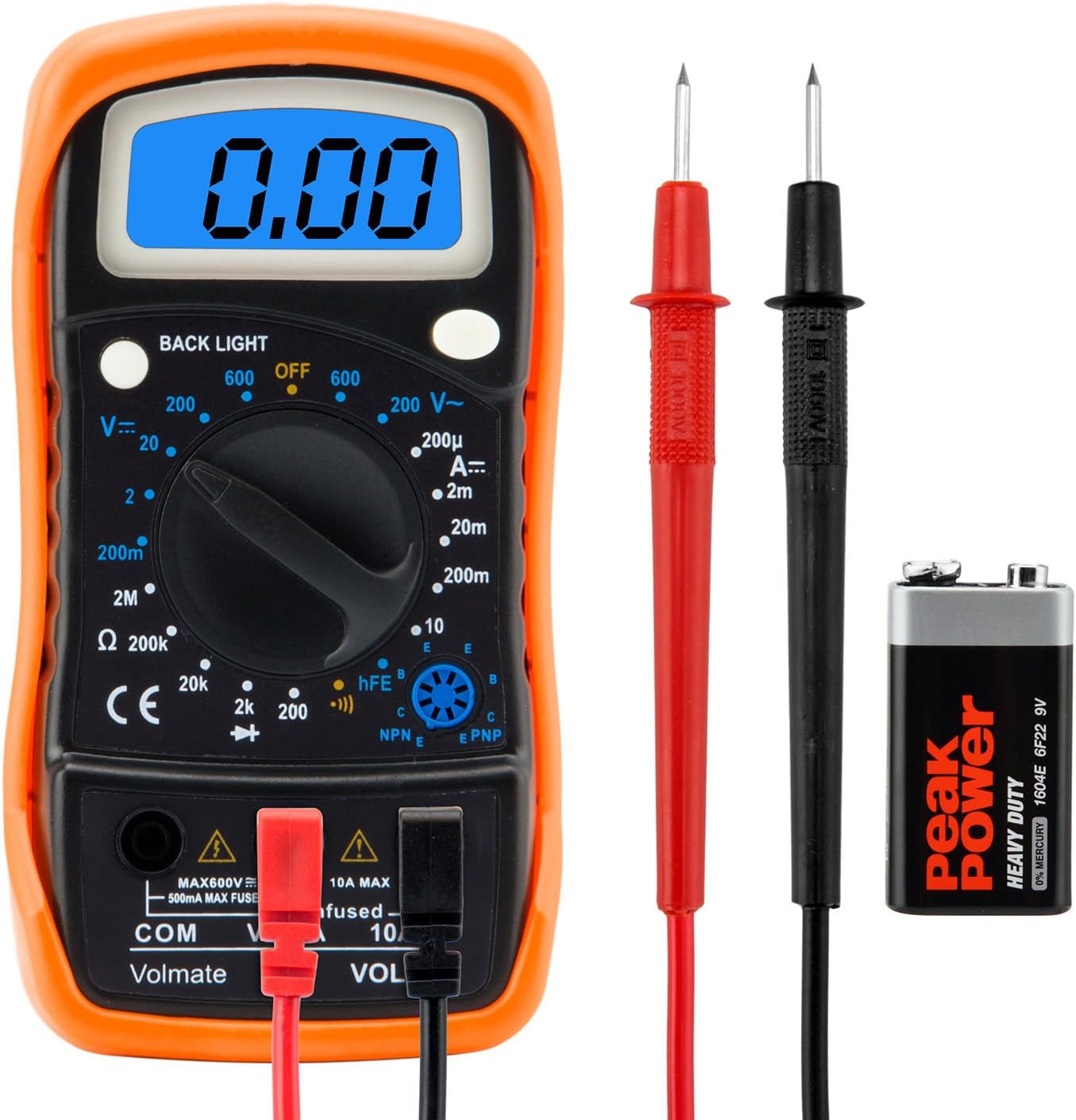
But a Voltmeter across the voltage rails could visualize if the uFs are too few.
If the needle stays still even during most powerful passages the capacitance is enough. If it bounces the capacitance is not enough to keep the voltage rails steady.
Am i wrong ?
Thanks and regards, gino
P.S. i am sure that this simple test would provide big surprises on most of the commercial amps, hopelessly underpowered. I am sure of this.
But a Voltmeter across the voltage rails could visualize if the uFs are too few.
An externally hosted image should be here but it was not working when we last tested it.
If the needle stays still even during most powerful passages the capacitance is enough. If it bounces the capacitance is not enough to keep the voltage rails steady.
Am i wrong ?
Thanks and regards, gino
P.S. i am sure that this simple test would provide big surprises on most of the commercial amps, hopelessly underpowered. I am sure of this.
Hi and thanks a lot for the valuable reply.

maybe
Thanks again, gino
and i understand that class A amps have many estimators. Maybe also this is a reason ? a steady voltage rail ?If the needle stays still then either you have a Class A amp
or the caps are far far too large
maybei think that we can agree that this not positive because changes the working point of the output devices. Can we agree on this ?Voltage rails for Class B will sag.
this is a good question. Not easy to answer i think.The issue is 'by how much?'
Thanks again, gino
i understand what you are saying but.....
isn't the % regulation spec of a transformer supposed to cover this?
do we really need to be this precise or meticulous?
can things be as simple as possible?
after all readers who are also diy'ers are not going to be interested in the
pure theory of things at the mathematical levels,
imho they will want to build practical amps that work without
being saddled with maths....
I'm a nerd. Show me the sine waves!
Class A may require a steady voltage, so it is fortunate that its steady current draw makes this easier to provide.ginetto61 said:and i understand that class A amps have many estimators. Maybe also this is a reason ? a steady voltage rail ?
No. The main problem with sagging is the clipping point reduces. Nothing to do with output stage working point.i think that we can agree that this not positive because changes the working point of the output devices. Can we agree on this ?
Fairly easy to get an approximate answer, which is good enough for most purposes.this is a good question. Not easy to answer i think.
Class A may require a steady voltage, so it is fortunate that its steady current draw makes this easier to provide.
No. The main problem with sagging is the clipping point reduces. Nothing to do with output stage working point.
Fairly easy to get an approximate answer, which is good enough for most purposes.
Hi and thanks again for the helpful advice.
But still i cannot feel the drawbacks of a too big PS capacitance.
Ok it is not neeed, but even detrimental for sound ?
I cannot see why really.
To oversize is quite common during design in general.
Thanks again, gino
According to the first few posts, that was actually supposed to be the topic of this thread.But still i cannot feel the drawbacks of a too big PS capacitance. Ok it is not neeed, but even detrimental for sound?
Cases where a too-small transformer attempting to maintain a lot of capacitance despite power amp also running, is probably just wishful thinking anyway.
Charge is spent to move the speaker, most likely a bass beat, which takes a lot of charge. The reservoir's charge must be recovered/refilled, instantly, prior to vocals and other higher frequencies. If the charge is not recovered in time (because transformer too small or too much capacitive delay), the result is muck.
To fix that problem, we could use any one of the following:
1). A bigger transformer
2). Less capacitance--smaller reservoir recoups charge more quickly
3). Front end on regs or other separation.
4). Running the amplifier at lower voltage than the reservoir (typical with regulators, but doable by many other means).
Last edited:
transformers have finite dc resistances, voltage will sag as more current is drawn...
also the mains voltage will fluctuate, it can go up or down, and with it your rails...
Hi and thanks a lot for the helpful advice.
Trivializing a lot the issue in general there is an ideal behaviour, non realistic of course, with the voltage that does not fluctuate, that does not sag.
And this i think is the reference anyway.
Again in general the more distant we are from the ideal behaviour the worse.
A better transformer with a low regulation will respond better to changes in current draw ...
If i see a needle that goes down a lot i would be worried.
IMHE the better amps had huge power supplies with huge transformers and caps.
Clearly a lot depends on speakers.
Thanks again, gino
According to the first few posts, that was actually supposed to be the topic of this thread.
Cases where a too-small transformer attempting to maintain a lot of capacitance despite power amp also running, is probably just wishful thinking anyway.
Charge is spent to move the speaker, most likely a bass beat, which takes a lot of charge. The reservoir's charge must be recovered/refilled, instantly, prior to vocals and other higher frequencies. If the charge is not recovered in time (because transformer too small or too much capacitive delay), the result is muck.
To fix that problem, we could use any one of the following:
1). A bigger transformer
2). Less capacitance--smaller reservoir recoups charge more quickly
3). Front end on regs or other separation.
4). Running the amplifier at lower voltage than the reservoir (typical with regulators, but doable by many other means).
Hi and thanks a lot and i think i see now better the point.
PS caps and transformer are interdependent.
Still i would do the test of connecting the analog voltmeter across V+ and V- .... for curiosity.
I am sure the best amps sag ... but very little.
So they are closer to the ideal.
Thanks again, gino
But the diodes only conduct when the transformers output exceeds the voltage on the caps, so you are usually not going to see the caps recharging until close to the peak of the next mains cycle.... The transformer has nearly nothing to do with supplying the required charge to the output devices, it is cut out of circuit by the rectifiers 80+ percent of the time, so how could it.. The reservoir's charge must be recovered/refilled, instantly, prior to vocals and other higher frequencies. If the charge is not recovered in time (because transformer too small or too much capacitive delay), the result is muck.
The designer should decide how much ripple is acceptable under full load and size the caps to suit, remembering that bigger caps beget smaller conduction angles in the rectifier and higher RMS/Average ratios for the currents in the transformer and rectifier, it is a simple calculation.
What is 'Capacitive delay', I have seen LC networks used for (short) delay lines, but a cap on its own?
Regards, Dan.
Approximately, the recoup time with a 100va transformer pushing 10,000u is similar to a 400va transformer pushing 40,000u.. . .What is 'Capacitive delay'. . .
However, in comparison, 100va pushing 40,000u won't be as clear* due to longer recovery time. *exceptions do exist.
P.S.
The examples are per each rail of a split rail supply for class ab audio amp.
My crude estimate of VA*123=uF (max per each rail) could be used to guess if a given transformer is too small for its supply; and, of course it is the same to figure out if the supply is too big for your transformer.
I am saying that figures too far beyond that estimate will do charge recovery too slowly for clear vocals and hf. But, that would happen to only the simplest approaches, and couldn't apply to something like regulated front end.
Hi and thanks a lot and i think i see now better the point.
PS caps and transformer are interdependent.
Still i would do the test of connecting the analog voltmeter across V+ and V- .... for curiosity.
I am sure the best amps sag ... but very little.
So they are closer to the ideal.
Thanks again, gino
yes Gino, once we have calculated actual circuit requirements, then we can start to think of ways to upsize things....the farther away we go from minimum requirements northwards, then the better imho...
diy'ers are not hindered by monetary considerations that commercial amp makers are always subject to...
Hi and thanks for the very valuable reply.
And actually the PS is IMHO the Achilles's heel of even not moderately priced commercial amps, and this reflects in the sound more than other things.
Never heard an amp with a great PS sound bad. Never. Maybe not perfectly transparent but always at least musical and in the end satisfactory.
Thanks a lot again, gino
Last edited:
Just curious: did you listen and form an opinion of the sound before or after looking and forming an opinion of the PSU? And you did back up your looking at the PSU with calculations of the likely voltage droop, ripple etc.?ginetto61 said:Never heard an amp with a great PS sound bad. Never. Maybe not perfectly transparent but always at least musical and in the end satisfactory.
It is easy to be impressed by the sound of an amp with huge caps and transformers, especially when you know they are present. Audio journalists do it all the time. Of course, caps and transformers need to be big enough - but beyond 'big enough' there is little advantage in going bigger apart from marketing purposes.
- Status
- This old topic is closed. If you want to reopen this topic, contact a moderator using the "Report Post" button.
- Home
- Amplifiers
- Power Supplies
- Power Supply Resevoir Size