i reassigned the "zen dual parallel single ended triodes with paralleled cathode followers" preamp to the duty of phono preamp.
the two circuit diagrams and the power supply diagram are shown below
i thought i could just stick with the old power supply and there would be no difference. wrong. now im getting only 80 volts B+ and low gain rather than 250 volts and too much gain.
i was getting 250v before but now it has all changed.
what do i need to do. change the resistors between the smoothing caps? any ideas?
thanks
Attachments
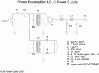
A centertapped rectifier cathode circuit supplying B+ from the CT? Show us the original diagram you're using to build from.
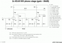
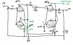
im not sure which original diagram you mean. those are the schematics for the one phonopreamp and the other is the diagram for the original preamp that was in the chassis.
A centertapped rectifier cathode circuit supplying B+ from the CT? Show us the original diagram you're using to build from.
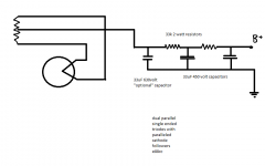
this is the PS that the designer suggests for this project. i thought one would be much like the other
Attachments
im not sure which original diagram you mean. those are the schematics for the one phonopreamp and the other is the diagram for the original preamp that was in the chassis.
Power supply diagram. Did you draw that from your own wire tracing?
this is the PS that the designer suggests for this project. i thought one would be much like the other
Your hand drawn PS diagram shows a directly heated K rectifier like a 5U4 or 5AR4 and your official diagram lists a 6CA4 type. And your hand drawn diagram shows you tapping the B+ from a CT on the 5V heater circuit for the 5U4. Aint no such thing.
Your hand drawn PS diagram shows a directly heated K rectifier like a 5U4 or 5AR4 and your official diagram lists a 6CA4 type. And your hand drawn diagram shows you tapping the B+ from a CT on the 5V heater circuit for the 5U4. Aint no such thing.
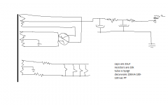
this is the complete schematic of the zen power supply that is in the original preamp.
the other PS schematic is the one recomended by the designer of the phono preamp
Attachments
this is the complete schematic of the zen power supply that is in the original preamp.
the other PS schematic is the one recomended by the designer of the phono preamp
So you are trying to use the RJM PS with the Zen preamp? Correct?
So you are trying to use the RJM PS with the Zen preamp? Correct?
nope the zen preamp PS with RJM phono preamp
nope the zen preamp PS with RJM phono preamp
The Zen PS drawing shows the rectifier output tied to a centertap of its own 5v circuit. Get that checked out. There should not be a centertap of the 5v. You may have some tranny legs crossed.
The Zen PS drawing shows the rectifier output tied to a centertap of its own 5v circuit. Get that checked out. There should not be a centertap of the 5v. You may have some tranny legs crossed.
what 5v. that is the B+ voltage. right on the rectifier, its about 600 volts pulsating DC . then after that goes back to the tranny that CT measures 400v before the smoothing caps and the 33k resistors. then between those resistors it's 250 and then only 90 for final B+. i need 250 for final B+ so can you help to determine what the value of those resitors should ought to be.
im sure that the final B+ supply was 250 with the other design.
thanks
LOL, you got it all wrong. Take a deep breath and start looking for your tube rectifier anodes.
what did i get all wrong
In your drawing it goes to the filaments, take your B+ from one side of the tube filaments. Pin 8.what 5v. that is the B+ voltage. right on the rectifier, its about 600 volts pulsating DC .
AC high voltage to the anodes, 5v to the filaments.
Last edited:
In your drawing it goes to the filaments, take your B+ from one side of the tube filaments. Pin 8.
AC high voltage to the anodes, 5v to the filaments.
which drawing? are you guys serious or not? i didnt mention any 5v no place and there is no 5v nohow.

my question is about the PS. why was there 250v with zen preamp and only 80v with this phonostage preampe thing.
Last edited:
which drawing? are you guys serious or not? i didnt mention any 5v no place and there is no 5v nohow.
my question is about the PS. why was there 250v with zen preamp and only 80v with this phonostage preampe thing.
Chop, the lines that go to pins 8 & 2 would have 5v on them for the filament/cathode but when it's running the full rectified voltage is on top of it so you'll never read 5v. there unless those leads are disconnected. It's the same for all 5Y3, 5U4, 5AR4... get it...they all start with 5. So if you get that sorted out and find out why your drawing has a centertap on there when there shouldn't be one, you may have a serious load on there drawing it all down. It should blow a fuse though if that's the case.
Anyway, realize that tranny is able to supply 150ma and the other tranny is only rated 50ma.
oh boy. i thought this would be simple.
that's right i have no idea how the filaments heat up in the rectifier tube. i have wondered about this. but im not blowing any fuses and the PS worked fine when i had the preamp set up. how does full voltage ride on the 5v, that's a new concept for me.
another finding. without the tubes installed i get 270 volts B+ and the caps stay charged. with the tubes installed there is only 90v or so and when i turn the unit off the capacitors discharge pronto like.
. this tranny is designed to be used with 240 volts also if that makes a diff
thanks
Those voltages are found with respect to ground of course. I just say that you would never see 5v there because everyone just checks there for normal voltages to ground. You have to go across the coils on the A/C setting with the tube out to see 5v. Anyway...it's interesting that you have the trouble with tubes in. Tubes have been known to short or when inserted in the socket the pins could push the soldertabs together and for a short...that's right i have no idea how the filaments heat up in the rectifier tube. i have wondered about this. but im not blowing any fuses and the PS worked fine when i had the preamp set up. how does full voltage ride on the 5v, that's a new concept for me.
If the tranny is dual voltage 120/240 you just need to make sure you are using the propper set of primary leads. Is it 3 or 4 primary leads? A switch? You probably have that right.
Last edited:
Those voltages are found with respect to ground of course. I just say that you would never see 5v there because everyone just checks there for normal voltages to ground. You have to go across the coils on the A/C setting to see 5v. Anyway...it's interesting that you have the trouble with tubes in. Tubes have been known to short or when inserted in the socket the pins could push the soldertabs together and for a short...
If the tranny is dual voltage 120/240 you just need to make sure you are using the propper set of primary leads. Is it 3 or 4 primary leads? A switch? You probably have that right.
if it was shorting wouldnt there be fuses blowing and light bulbs glowing brightly? there are four primary leads.
thanks
if it was shorting wouldnt there be fuses blowing and light bulbs glowing brightly? there are four primary leads.
The "short" is not always a dead short to ground. Plenty of other obstacles in a circuit. But if it's a reduced resistance...you get the idea.
Your primary connection is probably not the issue if it was working with the other preamp. Unused leads capped or N/C.
- Status
- This old topic is closed. If you want to reopen this topic, contact a moderator using the "Report Post" button.
- Home
- Amplifiers
- Tubes / Valves
- power supply reassignment problem