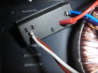
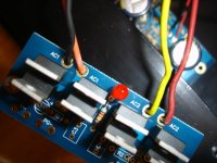
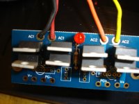
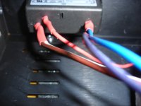
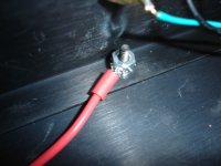
I would like to be sure that I am connecting the wires from the transformer to the correct locations on the rectifier board and power module.
Information off the transformer
View attachment 186180
Connections to the rectifer board
View attachment 186181
Connection to the power module
View attachment 186182
For the power module, I have connected the two negative (0) wires together and they are going into the (N) terminal. The two power (25V) wires together go into the (L) terminal.
I want to make sure things are wired properly, so not to blow it up or worse, get shocked.
Thanks.
Relinked
I would like to be sure that I am connecting the wires from the transformer to the correct locations on the rectifier board and power module.
Information off the transformer
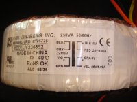
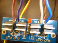
Connections to the rectifer board
Connection to the power module
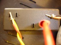
For the power module, I have connected the two negative (0) wires together and they are going into the (N) terminal. The two power (25V) wires together go into the (L) terminal.
I want to make sure things are wired properly, so not to blow it up or worse, get shocked.
Thanks.
I would like to be sure that I am connecting the wires from the transformer to the correct locations on the rectifier board and power module.
Information off the transformer

Connections to the rectifer board

Connection to the power module

For the power module, I have connected the two negative (0) wires together and they are going into the (N) terminal. The two power (25V) wires together go into the (L) terminal.
I want to make sure things are wired properly, so not to blow it up or worse, get shocked.
Thanks.
Definitely not correct. Assuming the block with the L and N is the power connection, the Blue and Violet wires should be connected together and go to the L connection, and the Grey (white?) and Brown wires connected together and put on the N connector (actually, they can go either way as long as gray and brown are together and Blue and violet are together) You also may want to put a switch somewhere in there - unless one is built into the power line module. For the secondary connections follow the wiring for this thread - they even use the same black,red, orange and yellow colors. http://www.diyaudio.com/forums/chip-amps/131820-help-first-power-supply-lm1875.html Lastly (and most important) set up a light bulb in line with the ac - more information can be found in the Power supply sticky at the top of the chip amp forum. Good luck with it. BTW, I've made some assumptions about the board and the power line connections but feel pretty correct about it.
Reaper, please be very careful. As you have it hooked up it is leathal. Please have it checked by a knowledgable person if you are not sure. sregor has put you on the right track but if you are not 100% sure take it to someone who knows this side of DIY and ask them to teach you. Otherwise you may meet your grim namesake.
I don't think so.
I will leave it to someone in the US to answer as I don't know that form of power entry module. Ours in Aus are different.
I think the rectifier bridge needs the wires in sequence Black, red, orange and yellow. Currently you have Black Orange, yellow red.
A bit of background while you wait
A power transformer has two 'sides'. We call these primary and secondary.
In the US the primary is the one labelled 110 or 115v This side goes in to the household power.
The secondary side is the side that goes into the toys we make. In this case 25V.
When you first connected it you had these the wrong way around. If you put 110V in the secondary you have over 500V coming out the other side.
Please wait for a response from the US. I am sure sregor will answer when he can. Patience is a virtue after all
Terry
FIRST!!!
build up a mains bulb tester and use it to power up your transformer.
If you have misswired the primary and/or the secondary, the bulb will light up and protect the transformer and rectifier from immediate damage and save your fuse/s from blowing as well.
If you do not understand how to wire up the bulb tester, get someone with the skills to do it for you.
do not take chances with mains electricity
Last edited:
FIRST!!!
build up a mains bulb tester and use it to power up your transformer.
If you have misswired the primary and/or the secondary, the bulb will light up and protect the transformer and rectifier from immediate damage and save your fuse/s from blowing as well.
If you do not understand how to wire up the bulb tester, get someone with the skills to do it for you.
do not take chances with mains electricity
But before I use the main bulb tester, don't I need to first wire the primary to the power source and the secondary to the rectifier board similar to the design on Nuuk's site?, http://myweb.tiscali.co.uk/nuukspot/...AQ.html#gcfaq1
Thanks for the replies.
Is this now the correct wiring of the power entry module and rectifier bridge?
power entry module
View attachment 186223
rectifier bridge
View attachment 186224
The power entry module looks correct; but, the rectifier bridge still looks wrong to me. According to the trafo picture in post #3 the 2 ac pairs should be AC1 = Blk-Red and AC2 = Ora/Yel. Other experts please feel free to comment/correct.
Hi,But before I use the main bulb tester, don't I need to first wire the primary to the power source and the secondary to the rectifier board
no, you don't need to connect a load to the transformer.
The bulb tester can be used to safely power up the mains transformer without damage.
If the bulb goes out, that usually indicates that the primary has been wired correctly. You can now measure the secondary voltages to see if they are what the specification says.
Then you can connect the secondaries to the rectifier. Power up again through the bulb tester. Again the bulb should go out and then you have time to check voltages.
Use the Bulb Tester for every new project and for every modification of any project.
Adding a load to your transformer counts as a modification. Adding smoothing caps counts as a modification. Adding the power Amp counts as a modification. get the message?
Do it all in stages and check each stage is behaving as expected. If you have made a mistake the bulb tester usually prevents any damage to the down stream components.
Practice using it regularly.
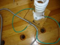
Like this:
View attachment 186270
It looks okay to me. I suggest you check the secondary AC before connecting to the rectifier board. Everything one step a time. What are PG+/-? Do you know how to connect them?
Okay, I have the bulb tester prepared and have soldered the primary wires to the power entry module. There is no load on the secondary wires, they are loose, do I need to secure the secondary wires or leave them like they are to test the primaries?
Is the CFL, 60 watt, ok to use for the test or do I need to use an incandescent bulb?
Thanks.
Is the CFL, 60 watt, ok to use for the test or do I need to use an incandescent bulb?
Thanks.
the tester must use a tungsten filament incandescent bulb.
Have a selection to hand for different power requirements.
I have 40W all the way to 150W. I test transformers and transformers + rectifiers with only the 40W bulb.
If I have a big capacitor bank to add on I may up this to 60W, but for first testing I never go as high as 75W.
These are all for the UK's 240Vac main supply.
I have no experience using the 110/120Vac supply.
- Status
- This old topic is closed. If you want to reopen this topic, contact a moderator using the "Report Post" button.
- Home
- Amplifiers
- Chip Amps
- Power Supply Questions
