Wait, wait, I’m not getting something. How do you get 440V from a doubler at the 220V AC tap? Shouldn’t that be actually 220*2*sqrt2?
How did you do the filtering of the output? CRC? What values did you use?
Still I wonder just how difficult I’d would be to design an smps. Safety is an issue. Been working on tube amps since I was 16. 20 years later I’m still here with more experience and much better tools.
What I would need is two fully separate and isolated secondaries, one 450 and the other 12.6V. The solution above would do that, but without the intellectual challenge of designing something from scratch. Ac/dc RCD flyback converter in one package would be nice, but the design of the coupled inductor might get difficult. Separate ac/dc offline or dc/dc converters seems like a viable option too. The latter could be powered by an old laptop PSU (19V @4.7A).
Obviously the proposed solution with a dc to ac converter is simple. I will order one and see how it works. I just don’t want to stop there as designing something myself (again) seems like much more fun (minimal 50% of the fun actually) to me.
Wait, wait, I’m not getting something. How do you get 440V from a doubler at the 220V AC tap? Shouldn’t that be actually 220*2*sqrt2?
Yes with a sine wave, however it's a square wave output. EDIT: I've actually got it set to 200V output for 420V out from doubler.
I'm using 22uF for the doubling caps, 47uF for the first reservoir cap, 620R, 47uF for the second RC. Oh and HER208 or UF5408 for the diodes.How did you do the filtering of the output? CRC? What values did you use?
Still I wonder just how difficult I’d would be to design an smps. Safety is an issue. Been working on tube amps since I was 16. 20 years later I’m still here with more experience and much better tools.
Easy to design a crap one, harder to design a good one
")
What I would need is two fully separate and isolated secondaries, one 450 and the other 12.6V. The solution above would do that, but without the intellectual challenge of designing something from scratch. Ac/dc RCD flyback converter in one package would be nice, but the design of the coupled inductor might get difficult. Separate ac/dc offline or dc/dc converters seems like a viable option too. The latter could be powered by an old laptop PSU (19V @4.7A).
Obviously the proposed solution with a dc to ac converter is simple. I will order one and see how it works. I just don’t want to stop there as designing something myself (again) seems like much more fun (minimal 50% of the fun actually) to me.
I hear that. For me that fun comes from designing unconventional amps, and cheap ways to power them
I use the 12V to power the heaters AND the boost module.
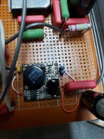
Here's a pic of a power supply using an ATX for 12V, a 12V-280V boost for preamps, a 12V-14.5V boost into a 12V-380V booster to give 440V.
View attachment 666919
See this thread for more details.
Ganged switching power supply for a tube amp.
Last edited:
I took the easy way out. Again! Bought me a 150W converter like you suggested/posted here.
Now for that doubler. I suppose I can just move 2 diodes of the bridge that is already present to the bottom and swap the other two for some 10-22uF/350-450V caps? I am currently looking at these caps: Panasonic EEU-EB2G100. 10uF/400V 250(!) mA ripple at 100 kHz. They look ideal for the job. Has going a step bigger any advantage at the frequencies involved?
The diodes on the board look to be HER207. Will this be good enough for just a preamp?
After the doubler there could be an RC filter. Series 47uF/400V (have 'm in stock) with 220k parallel to each cap. Final R value will greatly depend on the number of tubes being used. Currently 3 12ax7's (guitar preamp) but that might just as well double.
I just used what I had on hand, and I usually use the cheapest Chinese caps from eBay I can find such as these: 25V-450V High Frequency LOW ESR Radial Electrolytic Capacitor 10uF-10000uF LCD | eBay
I never thought of removing two diodes and replacing with caps since there's the AC output and diodes are cheap.
I have used one of these to power a preamp with 16 tubes that took about 200mA / 280V.
You can use an RC filter, but the filter in the preamp circuit should be plenty good enough.
I never thought of removing two diodes and replacing with caps since there's the AC output and diodes are cheap.
I have used one of these to power a preamp with 16 tubes that took about 200mA / 280V.
You can use an RC filter, but the filter in the preamp circuit should be plenty good enough.
Kodabmx, thank you for some interesting suggestions. I already have one of those lower power "ZVS capacitor charging 390V DC" modules, and now you've found a higher power solution that should be suitable for (valve) power amps too. Nice work!Then I still suggest you use one of these. <snip>
I'm cautiously skeptical of the 500 W rating (and the 42 amps of current it would take at 12V to supply 500 W even at 100% efficiency). But if the thing is good for even 100 watts, that should be plenty to power a valve guitar amp with, say, 40 watts output and the usual abysmal efficiency.
It's a really good thing that these high-voltage switching supplies are starting to be available and affordable, because traditional high-voltage 50/60 Hz valve power transformers are already on life support, only available at high cost from a handful of specialist suppliers.
-Gnobuddy
Kodabmx,I've used these. They are isolated, however they are adjustable which causes instabilities and oscillation if used with a choke input/crappy load.
I have used:
DC-DC 8-32V to 45-390V Step Up Power Supply Module High Voltage ZVS Boost Module | eBay
Not isolated, single ended design. I use one for powering a phono stage. More stable than the above.
DC-AC Converter 12V to 110V 200V 220V 280V 150W Inverter Boost Board Transformer | eBay
I prefer this design. It's isolated. I use them with a voltage doubler on the AC output to get 420V.
MINI DC-AC Inverter 12V to 18V220V/380V 500W Boost Step UP Power Module New Hot | eBay
I use these for power amplifiers. I'm using one to power a PP 6550 Amp. Runs with a 10 - 15 degree rise at 150W output.
Good afternoon,
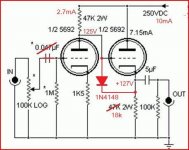
I'm a noob to tubes, been working on franks 6sn7 preamp.
I found this thread about you guys using these smps power supplies.
I tried Taylor 1364 HVPS seemed to work until I raised the bias of the amp. The amp started to squawl after a few minutes, I do not have an ocilloscope so I figured it's a power supply or the Russian tubes that have been using or maybe the layout of the amp itself and it is becoming unstable and oscillating?
How do you deal with the turn on thumb I get upwards of 35 votes DC on the output when starting up and shutting down?
Delay relay on the output?
I tried the above links to eBay on your isolated power supplies and the links are dead, I would greatly appreciate if you could send me some new links for eBay so I can try some of these power supplies for a preamp and you talked about using some in amplifiers.
Also what is elevating the heater supplies?
Just a noob trying to figure it out.
Any links to share on the subject.
What does your power supply lay out look like any information would be greatly appreciated.
Oh yes last but not least what are your favorite preamps and amp, no hurry with a response I may be asking too much here. LOL
But I would like to learn of your success in using such power supplies to reduce cost!
Thanks in advance Robert
Attachments
Here's a link to the 150W version suitable for a preamp: https://www.aliexpress.com/item/32760806274.html
Elevating the heaters means tying the heaters to the B+ theough a resistor divider to "elevate" the voltage so that your 12V heaters are sitting ~80V above 0V.
If you're getting 35V on the output on start and stop, you can strap a bidirectional TVS diode across the output to limit it to the diode voltage.
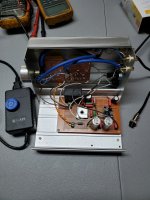
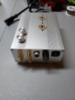
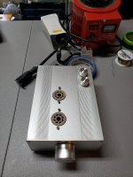
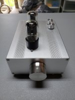
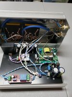
Here's a pic of a tube line/headphine amp built using one of the modules I linked, and a 12V 10A LED supply like this: https://www.aliexpress.com/item/1005002629988121.html

Elevating the heaters means tying the heaters to the B+ theough a resistor divider to "elevate" the voltage so that your 12V heaters are sitting ~80V above 0V.
If you're getting 35V on the output on start and stop, you can strap a bidirectional TVS diode across the output to limit it to the diode voltage.
Here's a pic of a tube line/headphine amp built using one of the modules I linked, and a 12V 10A LED supply like this: https://www.aliexpress.com/item/1005002629988121.html
Good morning Kodabmx,Here's a link to the 150W version suitable for a preamp: https://www.aliexpress.com/item/32760806274.html
Elevating the heaters means tying the heaters to the B+ theough a resistor divider to "elevate" the voltage so that your 12V heaters are sitting ~80V above 0V.
If you're getting 35V on the output on start and stop, you can strap a bidirectional TVS diode across the output to limit it to the diode voltage.
Here's a pic of a tube line/headphine amp built using one of the modules I linked, and a 12V 10A LED supply like this: https://www.aliexpress.com/item/1005002629988121.html
View attachment 1065931
I'm tracking the power supply you suggested,
Should be here in 5-7 days.
I have no scope so I rely on others fine tuning.
You suggested UF5408 fast diodes 75ns would it be better to use faster diodes, say
STTH3R06RL 35ns ?
My layout CRC will be as I seen in one of your post 47uf-620R-47uf will this be fine?I will be placing a final part order with Mouser soon.
Any further information would be greatly appreciated.
Thanks in advance Robert
Attachments
Either diode will work for you.
As far as the CRC filter, 47u - 620 - 47u worked for me, but it depends on what you're building I guess.
The module I linked will output DC @ 280V with it's built in HER208 diodes. http://malibor.by/sitedocs/12194.pdf
You can use any fast diodes you like on the AC output (1N4007 will burn out - too slow). You can also use the AC output to drive a multiplier.
It's for the preamp in post #28 that I attached.Either diode will work for you.
As far as the CRC filter, 47u - 620 - 47u worked for me, but it depends on what you're building I guess.
The module I linked will output DC @ 280V with it's built in HER208 diodes. http://malibor.by/sitedocs/12194.pdf
You can use any fast diodes you like on the AC output (1N4007 will burn out - too slow). You can also use the AC output to drive a multiplier.
I found it here.
https://www.diyaudio.com/community/threads/which-6sn7-preamp-should-i-build.71813/post-2255192
One again I appreciate all your help Kodabmx
....... Robert
Always worth reading == Jim Williams apnote AN118 == https://www.analog.com/media/en/technical-documentation/application-notes/AN118fb.pdf
high voltage low noise DC-DC converters. Merlin Blencowe also discusses voltage multipliers in "Designing Power Supplies for Tube Amplifiers, 2nd ed"
BTW, Analog Devices sells a development board for the LT3751.
high voltage low noise DC-DC converters. Merlin Blencowe also discusses voltage multipliers in "Designing Power Supplies for Tube Amplifiers, 2nd ed"
BTW, Analog Devices sells a development board for the LT3751.
Kodabmx,Here's a link to the 150W version suitable for a preamp: https://www.aliexpress.com/item/32760806274.html
Elevating the heaters means tying the heaters to the B+ theough a resistor divider to "elevate" the voltage so that your 12V heaters are sitting ~80V above 0V.
If you're getting 35V on the output on start and stop, you can strap a bidirectional TVS diode across the output to limit it to the diode voltage.
Here's a pic of a tube line/headphine amp built using one of the modules I linked, and a 12V 10A LED supply like this: https://www.aliexpress.com/item/1005002629988121.html
View attachment 1065931
Just wanted to touch base with you.
I appreciate all your help!
Finally got done tweaking this past weekend on the power supply.
Thanks again!!
.......Robert
Attachments
- Home
- Amplifiers
- Power Supplies
- Power supply options for tube preamp