The transformer only sets the upper limit of the current you can draw.With a 220 ma available current from the transformer, I have 1% of that as useable current- why?
Each resistor you put in series with the supply will drop some voltage (and 33K is very large): it's the ohm's law, V=RI, in this case V=33,000*0.0023=76V. Since you only have ~380V after filtering, this leaves you with ~300V (the exact figures have been computed by the simulator).
For a 50mA output, the total series resistance should not exceed ~1.5K, that should be spread as equally as possible to maximize the filtering.
Regarding the layout, past the supply itself the wiring should be star-fashion: daisy-chaining more or less randomly will only bring problems
I'm not sure what you mean by signal ground. Input signal ground? Output signal ground? Connection to chassis?aricaudio said:Power supply C.T.----1st cap gnd-----2nd cap gnd-----30th cap gnd--------------------------------------------------------------------------------------------------------------------------------1st cathod gnd-----2nd cathode gnd-----volume control gnd-----signal ground?
As a general rule (but rules are best avoided with grounding - think current loops instead) the ground for the circuit should either be a star or a bus which follows signal order. The connection between the PSU and the circuit ground should normally be at the point where the signal is greatest, so normally the output.
Here's the ground scenario
This can be changed. I'm trying to visualize how I'd physically ground the components. On the left two sockets, is the phono stage and the right two sockets are a line-stage.
All Inputs and Outputs are on the rear of the chassis.
The volume pot in the middle near the front is for an Opamp headphone circuit.
Volume's on the top left will be input, and output respectively.
If anyone's curious....on the sides of the preamp are Edcor balanced/unbalanced matching transformers.
Ignore the 8 pin socket in the middle- it's unused (originally the supply was going to be in this chassis).
The filament wiring is daisy-chained 18 shielded.
Attachments
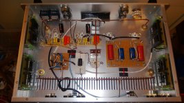
Currently the black wire (filaments) is just coiled up not terminated.
The blue wire is to the Phono stage Inputs.
The white wires run from headphone stage (it's basically a Cmos circuit), to a volume control on the input, and a transformer to convert signal to balanced.
That's just to give an indication of what the wires installed thus far are doing.
As far as the grounding, does anyone see a problem with using the copper wire as I'm using it? Could it possibly be as simple as connecting the ground wire from the power supply unit to the middle of this copper matrix?
High end signal means the part in the amp where the amplitude of the audio signal is highest, usually the output stage. It's the best part to 'join the grounds' as DF96 explained. If the same amount of noise gets coupled there, the signal-to-noise' ratio will be much bigger (bigger is better).
Best practice is to keep the transformer, big supply caps, etc. as far away from the input, where signal is the smallest.
IMO it's best to ground the specific given component to the point where they originally came from on the circuit. So e.g. a volume pot connected at the input but mounted in the middle of the chassis, should still be grounded at the input.
Alright cool ") So with having the volume grounded near the Input, and keeping that separate from high level signal ground (cathode, output volume control, etc.), we still have to run wires when the volume is mounted physically away from the Input connections, so then there's the loss or resitance of the wire that comes into play no doubt?
So with having the volume grounded near the Input, and keeping that separate from high level signal ground (cathode, output volume control, etc.), we still have to run wires when the volume is mounted physically away from the Input connections, so then there's the loss or resitance of the wire that comes into play no doubt?
So, say I had to run a wire all the way from the input volume control's ground, to the Input jack ground, how thick of a wire am I now using?
So with having the volume grounded near the Input, and keeping that separate from high level signal ground (cathode, output volume control, etc.), we still have to run wires when the volume is mounted physically away from the Input connections, so then there's the loss or resitance of the wire that comes into play no doubt?So, say I had to run a wire all the way from the input volume control's ground, to the Input jack ground, how thick of a wire am I now using?
In answer to how much current it will be carrying, I don't know the answer to that.
The volume control is already mounted, the RCA jacks are already mounted and a new chassis and layout is not an option.
That said, my last question was cut and dry and a request for specific information.
What gauge wire would be best to ground a volume control at the front of a preamp, to an Input jack on the rear of a preamp?
I would use the shield of the shielded cable carrying the signal. The RCA jacks should be isolated from the chassis. As far as possible the signal and the ground connection should run in parallel.
I can't tell you in detail how you should implement your design. That is part of the design process, and would require me to repeat all your design procedure. I can only tell you general principles. You can then apply them.
I can't tell you in detail how you should implement your design. That is part of the design process, and would require me to repeat all your design procedure. I can only tell you general principles. You can then apply them.
Drawing
Thank you I can understand more what you're saying now.
I'm sorry to seem (or be) thick, I'm just trying to picture what it actually looks like. I'm visual, and also a little too Artsy sometimes, so I tend to conceptualize more than one meaning for about every concept (or perhaps read too hard into some things, and not enough into others).
I do understand running power and signal away from each other, avoiding parallel runs, etc.
Dare I be so bold as to post a simply drawing and ask if this is on the right track?
Attachments
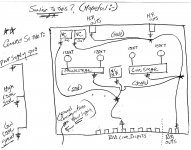
The connections in the picture aren't actually to the chassis, they are "stars" just shown for reference. In other words, all the low level signal ground go to one "star" point, the high level signal grounds go to another, then the power supply grounds go to a 3rd point, and all points are connected on a ground "bus" or bar. Then that bus get's grounded to the chassis through a "bridge" made up of a 10 ohm 10 watt resistor (in my case I used (2) 20 ohm 10 watters in parallel), and a 0.1 uf cap.
I "think" I basically have it, but I'll need to experiment to see if I'm implimenting the ideas posted by others correctly.
I "think" I basically have it, but I'll need to experiment to see if I'm implimenting the ideas posted by others correctly.
Also, I'm envisioning this right now, and was wondering, how about a copper electrical box bus??
So, run the bus bar down the center of the preamp- back end of it connects to power supply ground.
Then in the middle of it, all high level signal grounds go to a star point.
Then at the top of it, all low level signal grounds go to a star point.
Then it connects to the chassis through a bridge at.......the bottom.....or the top?
- Status
- This old topic is closed. If you want to reopen this topic, contact a moderator using the "Report Post" button.
- Home
- Amplifiers
- Power Supplies
- Power Supply for Tube Preamp