Okay, 'Plan 3' and another diagram reflecting the various kind suggestions made. (I've not found actual capacitors for the high/treble stage yet so thats just a guess -it could turn out to be a smaller number of bigger ones).
Does this look better now?
Cheers
kev
Does this look better now?
Cheers
kev
Attachments
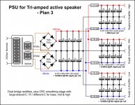
Most probably not bad at all. To be honest I'm not able to tell you, if this the best solution
for the given hardware and cost or if it's even better to just leave one pair of 4.700µF lytics
after the rectifiers and place the rest of them equally to all the three channels before the
resistors. Perhaps it doesn't even matter. The 0.1R already do provide some isolation between
the channels. A simulation will help, building both + measurements will clear things as well.
Now that I see the dual bridge, I can see that it does not solve the ground loop problem.
If the amplifiers have a common Signal Ground then that creates a loop through to the Power Ground.
Each would need a separate Power Ground and each Power Ground would require a Safety Disconnecting Network to PE on the Chassis.
I wonder if duplicating the dual rectifiers solves the loop problem with a set of active amplifiers?
Hmm, I think I see what you mean, though I still like the dual rectifiers a little better anyway.
Maybe it won't be so bad.. the ESP P101 amps have their signal ground separated from the main supply/star-ground by a parallel CR network which presumably should help.
The active crossovers that split the signal to the three amps will also be physically close, so perhaps with a bit of careful signal-cable routing there won't need to be be a huge loop formed. Probably I could directly share the star-ground point with the amps and crossovers.. in fact perhaps in that situation I wouldn't even need a separate signal ground between them (other than perhaps a shield connected at one end only), but I'm struggling to get my head around that at the mo, maybe it could make things worse..
Cheers
kev
Last edited:
Another way of looking at is if you need CRC or CLC filtering to isolate supplies the channels' control loops have inadequate PSRR. As has been pointed out on quite a few threads regulating input and VAS stages is cheaper than building up the supply and typically results in lower ripple at the power devices. Rather than devoting several thread pages to guessing you might want to run some sims or do the maths to see what's needed to meet your requirements for acceptable power supply artifacts on the output. You can search this forum for context; usually folks end up wanting 100 to 140dB PSRR.
Similarly, if loops in power ground are an issue then the control loops have inadequate CMRR. The easiest approach is usually to let the loops loop and use Kelvin sense to the output terminals to separate signal ground star from power ground star (it's often useful to expand this approach to introduce a ground stars for regulated control supplies and green ground for safety and shields). If you're unfamiliar with Kelvin sense, difference amplifiers, instrumentation amplifiers, and common mode servos there's an abundant literature available to consult about keeping difference amplifiers balanced and implementing high common mode input impedances.
Grounding shields at one end has a way of creating more problems than it solves. There's an abundant literature about this as well.
Bill Whitlock's done more than most to explain audio grounding, CMRR, and shielding. You might find a search for his AES presentations a useful starting point.
Thanks for that, TBH its going to take me some time to work through what you're saying and truly understand it, but I think I get the outline.
I think, given this is my first step into the field, that I'm happy enough for now with the amount and placement of capacitance that I/we ended up with. IIRC the amps aren't especially sensitive to power supply artefacts so I think its worth trying in practice - with my limited knowledge its likely to be a quicker and certainly more definite way for me to find out than trying to calculate all the subtleties.
Something similar may go for the ground loops too; I think in the first instance I'll try to do whats sensible in terms of routing/grounding cables (possibly with twisted pair to better use the CMRR) and hope the c/r isolation on the amps will make up for any small ground loop effects still surviving; if it doesn't then time for a plan B. I've some reason to hope it may be okay, as I see people have successfully used this sort of PSU configuration with these same amps for stereo configuration, with two separate line levels run to the amps from external sources, rather than closer ones using the same star earth.
I can see this is a bit 'suck-it-and-see' but having done the basic calculations and plans its quickly starting to get beyond my limited knowledge, so trying it out in practice may ultimately be quicker.
Cheers
kev
I will continue to contend that the ONLY reason we see and get away with small amplifiers on treble drivers is
because the sensitivity of treble drivers can be much higher than typically found in low frequency bass drivers.
Hi,
And you will continue to be wrong. Your arguments basically say
the same amplifiers are needed for a 100Hz/10KHz 3 way as a
300Hz/3KHz 3 way, and as such are simply pedantically wrong.
I've tried several times to explain the error of you ways but
its pointless with someone trying to insist something they
have always got wrong is in fact right, when it simply is not.
rgds, sreten.
Any rigorous analysis will refute that according to AT,
all pass bands, independent of bandwidth, and spacing,
and the number of them need the same amplifier rating.
Last edited:
Have you a measurement plan for establishing learnings or is this going to be sighted, subjective kind of thing?I can see this is a bit 'suck-it-and-see' but having done the basic calculations and plans its quickly starting to get beyond my limited knowledge, so trying it out in practice may ultimately be quicker.
Twisted versus untwisted has little effect the common mode noise sources which tend to produce the largest errors in audio circuits. So if you're counting on it to do something important it might be worth reviewing which noises require mitigation more carefully.
Any rigorous analysis will refute that according to AT,
all pass bands, independent of bandwidth, and spacing,
and the number of them need the same amplifier rating.
Do you have one?
Doesn't matter, really. There's sufficient diversity in power spectral density among musical passages any given optimization of amplifier sizing will end up non-optimal under some other circumstance. It's kind of like arguing about which teapot is best for accommodating tempests. ")
I suppose ultimately what I'm aiming for is subjective (something that sounds noticeably better than my current shop-bought set-up) so that will be the ultimate decider of success. But in initial testing I'll measure (as far as I'm able) what is going on in the signal path and supply voltages. Though it must be said that for me the emphasis will probably be trying to ensure it will work, that nothing is in danger of blowing up, and that I can't actually hear any artefacts or distortion; refinements beyond that will undoubtedly happen too, but I can't claim to have a structured plan for it at the moment.Have you a measurement plan for establishing learnings or is this going to be sighted, subjective kind of thing?
Twisted versus untwisted has little effect the common mode noise sources which tend to produce the largest errors in audio circuits. So if you're counting on it to do something important it might be worth reviewing which noises require mitigation more carefully.
I will be interested in testing the effect of various changes too though (e.g.) more/fewer capacitors, changing/bypassing the resistor between the smoothing caps and that sort of thing. At this stage I'm basing the initial design heavily on other people's expertise and opinion but from then I'd like to at least start gaining my own practical understanding of what differences things do/don't make - both subjectively and where I'm able in measurement.
Thanks for the info on the twisted pair too. I wasn't counting on it, it was just one thought of what I could potentially try if there was some sort of problem. I'm hoping there won't be anything that needs solving in practice, with the distance between crossover and the three amps being short and hopefully with half-decent management of earth points and cable routing.
Its a different issue, but I will probably use balanced XLR interconnects externally between pre-amp and speakers. The speakers could be quite a long way from the pre-amp and cable routing is likely to suffer 'aesthetic restraints', including being run along side the mains power supply cable in places too, so I suspect a balanced option may help avoid noise there.
Cheers
Kev
Last edited:
Hey Kev,
I use balance interconnects, plugged into the wall from the pre-amp and from the wall for the speakers. it works far better than unbalanced RCAs, far less noise. In fact, none that I can detect. I use Rod Elliott's balanced drivers and the crossover accepts a balanced input.
On the "older" note about what amps to use, I use the same amps for all drivers for one reason; it is easier to trouble shoot one type of amp than having different sorts of amps to sort out.
Some people try to make this whole process far harder than it needs to be, and then the arguments start about the right amount of pixie dust to spread on the angel wings and before we know it, a full scale brawl has started.
Thanks chaps! Heh, by coincidence it was Rod's/ESPs balanced transmitters and receivers I was intending to use, so its good to know they work
Yeah, I did previously consider using some class A amps for the tweeters, but decided against them for this particular application and certainly in terms of practicality I'm actually now quite glad to be using the same amp throughout. As you say, it simplifies things noticeably - one circuit to learn, buy for etc and there is also some economy of scale in certain components being cheaper in multiples. I'm also hoping that it will make matching the channels uncomplicated, though of course I'll still need to adapt to the relative sensitivities of the three drivers.
Cheers
Kev
Project 51? Depending on your gain structure and the difference in ground potentials spanned by your long runs upwards of 60dB CMRR may be desirable. So you might want to check out the Bill Whitlock references of post 26 and look at FDAs and purpose built line drivers and receivers before committing to a build. Rod's implementations are better than some but---like many line implementations---are both less matched and more sensitive to matching than necessary. This is getting OT for power supplies (line drive and receive probably fits best in analog line level even though it's mostly about dealing with the realities of grounding performance limits) but it's not hard to do better at managing ground offsets and other noise sources than project 51 at comparable cost and board area.
Last edited:
Its Project 87 I was thinking of for the balanced Tx/Rx, which supersedes P51 (though I think there are some more recent tweaks to the transmitter over that public version if you purchase the PCBs).
At the moment Rod's projects are a very attractive approach for me; I'm a novice in all this and there are so many aspects to the whole thing that it would take me years to learn what I need to know about everything involved. So I've decided to split my approach into two: firstly to get going with at least some help from projects and modules to hopefully achieve a rewarding initial result, and then secondly to come back again learning more by trying to improve on and further customise the initial setup. It sounds like Bill Whitlock's thoughts will be perfect for that, especially if I can actually hear any deficiencies related to my first implementation of the line driver/receiver.
Cheers
kev.
Last edited:
Yeah, the project 87A line driver topology tends to have stability problems due to its use of positive feedback. Parasound implements it with trim pots and Analog laser trims the SSM2142 to ensure adequate matching for stability. This is probably why the 87B circuit placed on the PCB is rather closer to the project 51 version. 87B is slightly better but suffers from the same linearity, matching, and output impedance limitations. All of the implementations Rod hosts are also noisier than necessary, partly due to component selection, partly due to lack of balance.
The 87A line receiver is a hacked instrumentation amplifier input stage, hence its gain restrictions and matching issues---the normal topologies follow a clean input stage with a difference amplifier for reasons you can read up on if you wish. Without your gain budget I can't say for sure but its likely a unity gain or attenuating line receiver is preferable to one with gain. As with line drivers if you want a turnkey line receive implementation you'd be better off copying the relevant application schematic from the datasheet of an IC built for the purpose.
The 87A line receiver is a hacked instrumentation amplifier input stage, hence its gain restrictions and matching issues---the normal topologies follow a clean input stage with a difference amplifier for reasons you can read up on if you wish. Without your gain budget I can't say for sure but its likely a unity gain or attenuating line receiver is preferable to one with gain. As with line drivers if you want a turnkey line receive implementation you'd be better off copying the relevant application schematic from the datasheet of an IC built for the purpose.
Interesting stuff, many thanks; I can see that I've a lot to learn here - the initial build looks very much like it will just be the beginning!
One good thing is that Rod's Tx/Rx circuits look pretty easy and cheap to build so it'll be interesting (rather than costly) to see how they perform and/or experiment with alternatives. The mosfet amps I'll be using are reputed to be fairly quiet too, so noise from the interconnects should stand out reasonably well - especially as these will be after the pre-amp stage, so any noise won't be attenuated with volume.
Cheers
kev
But they work really well, the PCBs are good and you get support.Yeah, the project 87A line driver topology tends to have stability problems due to its use of positive feedback. Parasound implements it with trim pots and Analog laser trims the SSM2142 to ensure adequate matching for stability. This is probably why the 87B circuit placed on the PCB is rather closer to the project 51 version. 87B is slightly better but suffers from the same linearity, matching, and output impedance limitations. All of the implementations Rod hosts are also noisier than necessary, partly due to component selection, partly due to lack of balance.
The 87A line receiver is a hacked instrumentation amplifier input stage, hence its gain restrictions and matching issues---the normal topologies follow a clean input stage with a difference amplifier for reasons you can read up on if you wish. Without your gain budget I can't say for sure but its likely a unity gain or attenuating line receiver is preferable to one with gain. As with line drivers if you want a turnkey line receive implementation you'd be better off copying the relevant application schematic from the datasheet of an IC built for the purpose.
I doubt you will hear any noise. I use them and don't but, then again, I don't have Golden Ears, just ordinary human ones.Interesting stuff, many thanks; I can see that I've a lot to learn here - the initial build looks very much like it will just be the beginning!
One good thing is that Rod's Tx/Rx circuits look pretty easy and cheap to build so it'll be interesting (rather than costly) to see how they perform and/or experiment with alternatives. The mosfet amps I'll be using are reputed to be fairly quiet too, so noise from the interconnects should stand out reasonably well - especially as these will be after the pre-amp stage, so any noise won't be attenuated with volume.
Abs
- Status
- This old topic is closed. If you want to reopen this topic, contact a moderator using the "Report Post" button.
- Home
- Amplifiers
- Power Supplies
- Power Supply for tri-amped speaker