I know this will sound pretty lame but I need to ask it ")
Anyone can show me how to build a power supply to drive a STK4048XI?
I have to PCB already mounted by a guy I lost trace of and I didn't ask him to supply me the information of how to design and build the power supply that go with the PCB...
With transformer to use? with rating?
The schematic and even better the schematic and the PCB layout for the power supply? anyone can help?
Thanks in advance,
Francois Gregoire
here is the Datasheet for the chip
http://home.eunet.cz/rysanek/pdf/stk4048XI.pdf
There's a power supply schematic included in the datasheet. Are you meaning you need some help with it ? (located just below Operating characteristics)
The stk4048 is a pretty crazy component (and a crazy transformer)....
Never heard of it until your post but it deserves some experiments.
Well, the maximum voltage is being +-87V, you'll probably want to stay around +-65V (220W, THD 0.008%, 8ohms load) so I suppose you'll need at least 700-800VA transformer with 2 X 50V secondaries per monoblock with huge capacitors
It's gonna be a monster. (don't forget those heatsinks that will need to dissipate around 120-130 Watts !!!)
Ask if you need any further help !
Regards,
Yes I need help
Cause i erally a newbie in designing thing in eletronics.
Give me a blank PCB and the component and I will build some stuff but starting from scratchs, that a different story
What I need is the exact component needed so I can try to design the PCB myself after...
Can you help me learn do to it?
Francois
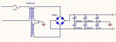
Two rectifiers, a few caps, and a transformer with two windings.
50V transformer sounds OK, a coupla KPBC rectifiers, or schottkys/ultra-fast diodes if you want, no schematic is really needed, neither is a PCB. Use nice high-current wire, as the STK pulls quite a few amps at full load.
Elkaid, watch out: there are two of these guys, the 4048V, 4048X and 4048XI. Please get only the XI. distortion figures and internal curcuitry are the best in this one.
Thanks for the hint
Still, those chips are litterally crazy
Dark Shadow : With the size of the transformer needed in your project, you'll probably need a soft-start circuit to prevent fuses from blowing up when turning on the amplifier. A circuit is described here.
You can also do a quick search on the forum, you'll probably find other schematics.
As Sangram said, it is NOT recommended to use a PCB for your power supply considering the current implied.
Here's a simple schematic (Please note that electrolytic capacitors are rated at least 80V. (if you can afford 100volts...)
Attachments
Also, do you have any sources where you can get those STK4048XI ?
I found a distributor here
but they're 30$can.
10000uF capacitors will be around 20$can each (digikey)
For the transformer, I suggest Plitron (www.plitron.com) or Hammond (www.hammondmanufacturing.com available through www.digikey.ca)
Regards,
I found a distributor here
but they're 30$can.
10000uF capacitors will be around 20$can each (digikey)
For the transformer, I suggest Plitron (www.plitron.com) or Hammond (www.hammondmanufacturing.com available through www.digikey.ca)
Regards,
Hi Francois,
These STK chips are not really rated for continuous max rated power, especially into lower impedence loads - 6 ohms etc.
In the applications that I see high power STK modules, fan forced cooling is used.
Also they are typically used with under-rated transformers.
The purpose of this is to cause (allow) the power rails to sag somewhat under max power delivery, thus causing a natural soft limiting of output power and dissipation.
I would use seperate transformers for each rail, and each transformer rated at 150 VA or so, per amplifier channel.
At this VA rating, you can run secondaries of around 50-60 VAC, giving DC supplies of 70-84 VDC (VDC=1.41 x VAC).
With this VA rating of transformer, DC sag will be fine.
Be sure to use heatsink grease, and sand both heatsink surfaces against very fine wet&dry paper against a thick block of glass to MAKE SURE that both surfaces are precisely flat.
These things are relatively fragile, so DO NOT short the outputs.
If you build this carefully, paying good attention to intelligent earthing arrangements, you should build a very fine amplifier for yourself.
The price in AUS is around AUS$28.00.
Eric.
mrfeedback:
I'm already planning to lap the STK and the heat-sink to get better heat transmission. Also I will use Artic Silver compound instead of the basic zinc composed one. Again better transfert.
If I understand you correctly, you suggest to use two transformer for each chip? So if I want to make a stereo package, that mean 4? (with is not the case, I want to make one to be used as a subwoofer amplifier for my Home theater setup).
Yup two transformers per channel, or one per rail at least for a stereo amplifier chassis.
If you take care with correct central earthing and this works best.
Two lesser rated EI transformers can probably be found for less cost than one CT torroidal, and gives two truly independant DC rails.
Eric.
If you take care with correct central earthing and this works best.
Two lesser rated EI transformers can probably be found for less cost than one CT torroidal, and gives two truly independant DC rails.
Eric.
i built 2x150w 19' rack amp with it
sound great!!
at the first stage im controlling the signal with tl072 and then the signal goes to the stk. i have the 4048 2 ver not the 5 it has 0.4%thd.
the power sup is consisted with 300w transformer and 2 10000uf 100v capacitors and it holding just fine. i can add 2 more capacitors for more voltage stability but i dont need too..im not getting close to 150w its for home studio use...connected to my mixer,dvd and synthesizer...
the heat sync is not so large but both of it has 12v computer fan on it and placed to the ic with heat sync compound
and i can touch it its not getting too hot.
i built control circuit to soft start the amp and drilled holes in the heat sync for 2 temp control resistors to disconnect the out pot in case of over heat and circuit to disconnect the output in case of dc volts to the speaker...
im happy
stk4050 and stl4048
The power supply is very basic. The problem is the transformer and caps they can end up costing you alto. www.plitron.com has a 2.2kva on sale for $85.00 that’s a steal!!!
The Sanyo site has all the data you need. If you google the stk4048 it also has the pcb layout.
The stk 4050 and stk 4048 use all the same components so you can swap one or the other. Good luck, Dave
any questions just ask !!!1
- Status
- This old topic is closed. If you want to reopen this topic, contact a moderator using the "Report Post" button.
- Home
- Amplifiers
- Solid State
- Power Supply for STK4048XI