Hi Damir,
This is a nice solution to a problem I have been trying to solve with my latest amplifier. Could do with higher voltage rails but I suspect this can be easily achieved.
Do you have a latest version or is the version in your TT amp thread the final solution?
Paul
Hi Paul, it's easy to do with higher voltage, just need to change some elcos for higher voltage and some bjts.
The last version is in my TT amp tread http://www.diyaudio.com/forums/solid-state/182554-thermaltrak-tmc-amp-22.html#post3907062.
You need to have 5-7 voltage drop on the pass transistors and use R22, R23, R122 and R123 to adjust that and then the output voltage is going to be for that much lower then input voltage, and that depends of the chosen transformer voltage.
Damir
Thank you Damir.
Your designs and ideas are always very elegant and imaginative.
")
Is it ok to use this for my amplifier creation?
Paul
This shares some similarities with the capacitance multiplier + regulator (over voltage protection) that I designed here:
http://www.diyaudio.com/forums/powe...tance-multiplier-over-voltage-protection.html
http://www.diyaudio.com/forums/powe...tance-multiplier-over-voltage-protection.html
Thank you Damir.
Your designs and ideas are always very elegant and imaginative.
Is it ok to use this for my amplifier creation?
Paul
Hi Paul, feel free to use it for what ever amp you want.
By the way how is going with the GainWire, did you listen to it in big system?
Damir
This shares some similarities with the capacitance multiplier + regulator (over voltage protection) that I designed here:
http://www.diyaudio.com/forums/powe...tance-multiplier-over-voltage-protection.html
Adding the zeners parallel to the base capacitance makes it not capacitance multiplier but fixed voltage regulator.
Adding the zeners parallel to the base capacitance makes it not capacitance multiplier but fixed voltage regulator.
Not always. It depends on how they are implemented in the circuit and what voltages are being regulated.
For instance, if the incoming rails were always higher than the regulation voltage then, yes, you would always have a regulated output. This is not the case for my application. Under no load, the incoming rails are higher than the regulation voltage by about 7V and you get a (lower) regulated output. Under even a moderate load, the current draw is enough to drop the incoming rails (from the smoothing caps) below the regulation voltage, and then the capacitance multiplier part of the circuit takes over and the output rails are like a smoothed average of the incoming rails, which have increasing ripple.
This circuit arose out of DIY needs - it allowed me to use an existing transformer with a particular amplifier board when, without the addition of my circuit, the no-load rail voltage would exceed the maximum allowed. More generally, this approach works well with a slightly undersized transformer (lower VA) that has a slightly higher secondary voltage. The zener regulation part of the circuit also provide some control of the rail voltages in the case that the mains voltage climbs (in my my area the mains voltage is about 7% higher than nominal).
OK, I see now it was design for undersized transformer with to high output voltage, a bit strange for me. A weak transformer will never deliver as good sound as one powerful enough.
A weak transformer will never deliver as good sound as one powerful enough.
In my opinion, this is somewhat of a mistruth, depending on what you mean by "weak". I never said that my transformer was "weak". Every transformer has the behavior in which the secondary voltage sags as current is drawn (amp output power is increased). Even if you over size your transformer by 10x the amp output power into load, there is still some slight sag under high power demand. So how can this property be made more useful? Well, you can think a transformer like I have described in a different way - as a power supply that can provide high short term peak power and lower constant power. This is, in fact, exactly what high-fidelity (non compressed) music signals are like. I don't need my amp to be able to deliver 500W all the time, only for brief periods of time when there is a peak. Using a smaller transformer with a higher secondary the amplifier and PS can be designed so that these brief peaks are cleanly reproduced while the lower constant power requirements are still easily met. This is exactly the approach that I am using with my PS board. If you need 500W all the time and don't want the rails to sag, then buy/build an amp with a switching power supply.
Last edited:
In my opinion, this is somewhat of a mistruth, depending on what you mean by "weak". I never said that my transformer was "weak". Every transformer has the behavior in which the secondary voltage sags as current is drawn (amp output power is increased). Even if you over size your transformer by 10x the amp output power into load, there is still some slight sag under high power demand. So how can this property be made more useful? Well, you can think a transformer like I have described in a different way - as a power supply that can provide high short term peak power and lower constant power. This is, in fact, exactly what high-fidelity (non compressed) music signals are like. I don't need my amp to be able to deliver 500W all the time, only for brief periods of time when there is a peak. Using a smaller transformer with a higher secondary the amplifier and PS can be designed so that these brief peaks are cleanly reproduced while the lower constant power requirements are still easily met. This is exactly the approach that I am using with my PS board. If you need 500W all the time and don't want the rails to sag, then buy/build an amp with a switching power supply.
Good points, just I don't have listening experience with this approach.
Smaller voltage drop on MOS regulator
Hi Damir,
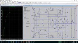
I was playing with your MOSFET PS regulator and my simulation is showing that I can reach voltage drop between input and output very small - less than 2V. I made it via changing values of resistors at input divider i.e. R1=12k, R18=12k and R2=22k. Is there any practical risk to assemble it this way?
Thanks,
Ladislav
Hi Damir,
I was playing with your MOSFET PS regulator and my simulation is showing that I can reach voltage drop between input and output very small - less than 2V. I made it via changing values of resistors at input divider i.e. R1=12k, R18=12k and R2=22k. Is there any practical risk to assemble it this way?
Thanks,
Ladislav
Attachments
Hi Damir,
I was playing with your MOSFET PS regulator and my simulation is showing that I can reach voltage drop between input and output very small - less than 2V. I made it via changing values of resistors at input divider i.e. R1=12k, R18=12k and R2=22k. Is there any practical risk to assemble it this way?
Thanks,
Ladislav
Hi Ladislav,
This is not good approach, you need some margin to regulate in case of high load. Yu have to take in account that input voltage is not pure DC, it has 100Hz superimposed coming from a rectifier with big caps, with higher amplitude as the load get heavier. That is why it is called regulator.
BR Damir
- Status
- This old topic is closed. If you want to reopen this topic, contact a moderator using the "Report Post" button.
- Home
- Amplifiers
- Power Supplies
- Power supply cap multiplier with electronic protection