Hi
Since there is nothing like this for supplys,I am making one here.This is because I would like to see what does everyone else have.This might be supply for amps,regulated bench, chargers... and Pfc's too.For supply it is prefered switched mode one, that you made or bought.
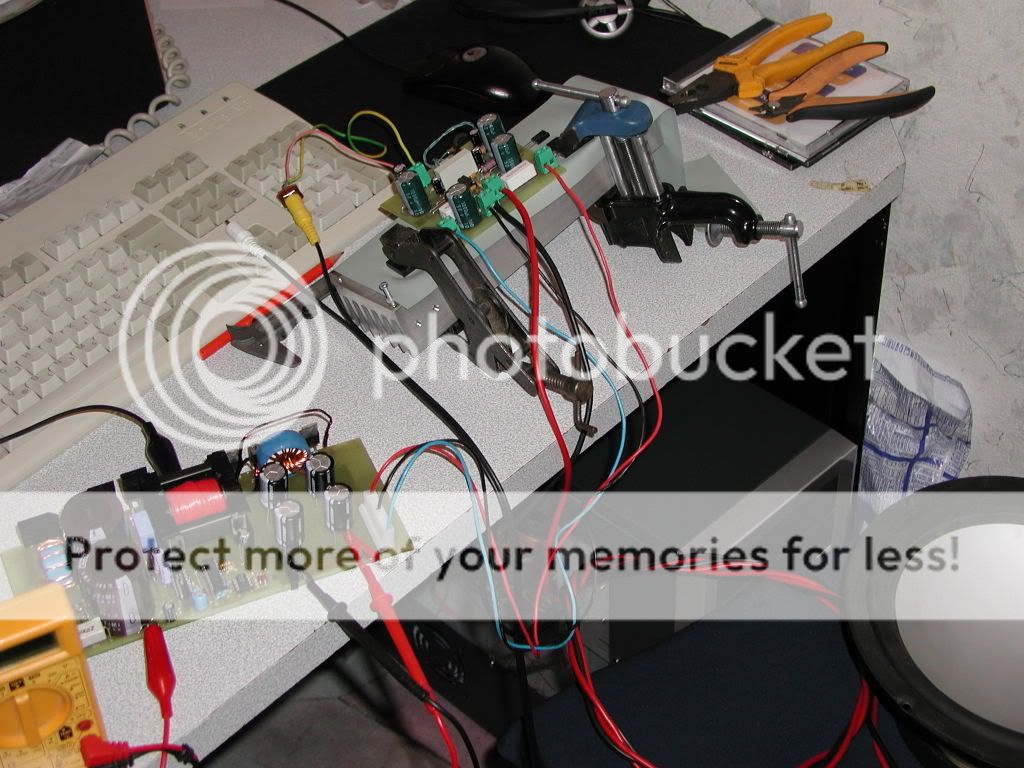
I'm posting here my smps that will power 2x TDA7294 and 2x LM3886, all with 4 ohm loads. There is no PCF for now...
Since there is nothing like this for supplys,I am making one here.This is because I would like to see what does everyone else have.This might be supply for amps,regulated bench, chargers... and Pfc's too.For supply it is prefered switched mode one, that you made or bought.
I'm posting here my smps that will power 2x TDA7294 and 2x LM3886, all with 4 ohm loads. There is no PCF for now...
Luka-
Looks really cool.
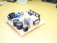
Here is one I did (more than) a few years ago. Rated at 185W, its topology is boost and control technique is CrCM (Critical Conduction Mode). Controller is MC33262, MOSFET is MTW20N50, diodes are MUR8100s and caps are Panasonic TSNH series, 390mF, 250V (in series). Worked for about a minute before it blew a 10A slow-blow fuse. Haven't powered it up since then.
I need to take a serious look at the UC3854 CCM PFC Chip. Since it runs constant frequency, it should easily be synchronizable to whatever PWM chip I choose for the DC-DC stage.
Steve
Looks really cool.
Here is one I did (more than) a few years ago. Rated at 185W, its topology is boost and control technique is CrCM (Critical Conduction Mode). Controller is MC33262, MOSFET is MTW20N50, diodes are MUR8100s and caps are Panasonic TSNH series, 390mF, 250V (in series). Worked for about a minute before it blew a 10A slow-blow fuse. Haven't powered it up since then.
I need to take a serious look at the UC3854 CCM PFC Chip. Since it runs constant frequency, it should easily be synchronizable to whatever PWM chip I choose for the DC-DC stage.
Steve
Attachments
For the same reason you want to synch two PWMs in close proximity: to eliminate beat frequencies from their two oscillators running at nearly the same, but not exact freqs. The difference between the two is the "beat", and if it is low enough, it can get into the audio band.
A CCM PFC oscillator's frequency is determined by load, so it can vary by a 5:1 margin. A CrCm runs at fixed freq, so synch'ing it to the PWM (or the PWM to the PFC) will eliminate this beat. There are several threads in the Power Supply Design forum on this.
Yeah, it was kinda cool. The Professor took one look at it and gave me an "A". Didn't even ask me to power it up. Whew! He said it looked so cool, he gave me the "A" on the looks alone. Think, it could have been a motor control board, and he would liked it!
luka said:Hi
I defenetly can see why he gave you an "A"
One more thing. So if I have 2xD-amps, 2xSmps for amps and PFC at inputs of smps's, I would need to sync all of them?
How would I do that, since amps would be running ~250kHz, smps's ~50kHz and PFC ~100kHz?
I think you would start off with the D-amp, do a 2.5:1 ratio for the PFC, then a 2:1 for the smps. That way they all get triggered at the same time and no beat frequenceis should be present.
Thats how I understand it.
BTW how do you make such a sexy looking boards you guys??
I'm always having issuse with missing traces or down-right ugly looking projects.
luka said:Hi
It takes some time, but it is just trial and error. What do you use to make them?
Well the first ones I made at school I don't remeber what was used, all I know is after a few boards the water/chemical was all blue.The stuff I have now(haven't used yet) is some etching stuff from radioshack
I'm not 100% sure what it is but it does say this on the bottle
Contains Ferric Chloride and Hydrochloric Acid in aqueous solution
N-Channel said:
A CCM PFC oscillator's frequency is determined by load, so it can vary by a 5:1 margin. A CrCm runs at fixed freq, so synch'ing it to the PWM (or the PWM to the PFC) will eliminate this beat. There are several threads in the Power Supply Design forum on this.
B]
I goofed: a CrCm (Critical Conduction Mode) PFC's frequency vaires by a 5:1 margin, and the CCM (Continuous Conduction Mode) runs at fixed frequency. Got'em backwards. Doh!
ifrythings said:
BTW how do you make such a sexy looking boards you guys??
I'm always having issuse with missing traces or down-right ugly looking projects.
It's a good thing I didn't show the underside.
Too much solder (my lame-a$$ attempt at "wave soldering"), and oxidation where no solder.Luka,
As you can see from my pic in post #2, the input rectifiers I chose were TO-220AC cased MUR8100s. I chose these because of their reverse-recovery time (Trr), and because of the high-frequency pulses, modulated at 60Hz (50Hz for Europe, elsewhere), being drawn through them. Eva commented on the use of these a while back, and I think she said something like: if CCm was being used, then the rectifiers could be standard-recovery, because the high-frequency pulses were no linger a factor, or something like that.
Anyway, 1000V diodes were chosen so I wouldn't have to mess with changing 400V or 600V diodes to 800V units if powering off 220-250VAC lines. Forfgot to mention- the inductor came from Coilcraft. It was specifically designed to be used with this PFC chip (MC33262). Since then, I have read alot of CCM PFCs at 300W and above, so I think I will go that way, instead.
my amp8 while still under bench testing.

the SMPS is the leftmost module. the T amp at the middle and control board at the right.
the SMPS was designed to do 1200W (at the time, later rewound to do 1500W) taking in 12VDC at >100A and +/-55VDC out.
it uses a conventional unregulated design with 10940uF per rail, TL494 oscillator, 14 IRFZ44 fets and four 60A Ixys ultrafast rectifiers.
luka said:Hi
I defenetly can see why he gave you an "A"
One more thing. So if I have 2xD-amps, 2xSmps for amps and PFC at inputs of smps's, I would need to sync all of them?
How would I do that, since amps would be running ~250kHz, smps's ~50kHz and PFC ~100kHz?
Luka-
Since your SMPS is running at 50kHz switching frequency, that means your PWM's oscillator is clocked at 100kHz, so synch'ing it to the PFC won't be difficult. (Remember, 2 clock pulses for each switching cycle.) Then do the 2.5 to 1 frequency divider that ifrythings suggests. If you can't get a frequency divider to divide by fractional numbers, then do a 3 to 1 frequency divider and clock your T-amp at 300kHz.
ifrythings said:
The stuff I have now(haven't used yet) is some etching stuff from radioshack
Fry-
I have used the Radio Skank etchant for about 15 years, now, and have had anywhere from poor to excellent results, giving creedance to Luka's statement of trial-and-error. It DOES take time to get experience, but as your experience handling FeCl3 with copper boards gets more, it will also get proportionally better.
Luka-
Yes, I still have it. I would like to get a BIG iso-trans before I plug it in again. The circuit I used basically comes from Brown's chapter on PFC'ing. I think this is where I got the notion of using ultra-fast rectifiers off the AC line. The only difference I did from Brown's circuit was that I split the output cap into two series caps (w/balancing resistors) to provide a Vout/2 reference for doing half-bridges.
N-Channel said:Who Cares! I just like the Blue LEDs!
I just got the toroids off a junk pile.
 it measures around 2.5" ext dia, 1" tall, and the inside dia is about 1.25". there are no coatings, just bare ferrite so I wrapped it in paper before winding since bare ferrite strips the enamel insulation off copper wire.
the TL494 runs at about 60kHz so that's about 120kHz clock. the SMPS is running fixed and not synced to the T amp but I have no problems with beat frequencies.
the control board on the right also has an onboard independent SMPS with +/-15V and +5V for the preamps and tripath chipset. it runs at about 28kHz (56kHz clock) with an RM core. (also took that off a junk pile
) the large difference in frequency reduces the chance of getting a beat frequency with the main SMPS and luckily, those were the most efficient operating frequencies of both the small and large transformers.my 12" subs are crying because of the power output so I got a bigger 15" sub. will install it in a few weeks after the exams.

each toroid has two primaries and one secondary.
the primaries are connected in series then the two transformers connected in parallel to common banks of fets.
the secondaries of both toroids are connected in series to get a center tap.
I have 6+6turns for each primary and forgot the turns for the secondaries.
I'm now using 11 conductors per winding in the primary (different from the pics, have rewound them since then) and 9 conductors per secondary. 1 conductor = #21 enamelled wire
djQUAN said:
I just got the toroids off a junk pile.
DJ-
I'm hanging out in the wrong junk piles
Steve
I have built up a nasty habit of buying toroids even if I don't have any need so now I have around 15+ large toroids that are suitable for push-pull SMPS's since that's what I often build.
to think, toroid cores are VERY hard to come by over here. it's just that I have accumulated so much over buying even when not needed. hehehe. the thought of "I may need that someday!" keeps me going.
to think, toroid cores are VERY hard to come by over here. it's just that I have accumulated so much over buying even when not needed. hehehe. the thought of "I may need that someday!" keeps me going.
- Status
- This old topic is closed. If you want to reopen this topic, contact a moderator using the "Report Post" button.
- Home
- Amplifiers
- Power Supplies
- Power Supply and Pfc Photo Gallery