BWRX - thanks, revised version done. Data sheet has lots of applications, not sure which is relevent. Im thinking a zener will give a more precise reference.
richie00boy - yes, i have dual secondaries.
AndrewT - im living in Edinburgh whereabouts are you?
Reason for regulating - im hoping that if i drop the voltage, i will have some power in reserve for loud passages of music. I don't want a loud bass passage to effect the power to the treble amps.
I'm making a 4xmono amp. A quad amp if you like. With separate power supplies, so im thinking a more more precise, equal and stable supply is not a bad thing.
Im not looking for party level volumes.
Nordic - http://pedjarogic.com/gc/supplies.htm thats were i stole the idea. I would like to make changes so it is at least part original
For people who have tried with and without - What we really need to establish is the difference in sound a reg makes. Some say better, some worse. Is the response time good for this reg? I mean does the sound loose the sharp transients? Can it deliver the power quickly? Are transistors faster? I suppose you still have the caps at the amp chip for sudden demand.
When is it good to regulate? and when a waste of money and time.
This forum is great. everyone friendly (most of the time when ego is not in control) and helpful. If only you were real people!!
Attachments
Hi Wooly,
you MUST have a voltage drop across the regulator.
Expect about 2V to 3V below the voltage at the bottom of the ripple coming from the PSU when demand is at it's highest.
If your supply with just quiescent current flowing is 27Vdc and ripple is 10mV then the lowest voltage at the amplifier is 27-(0.5*0.01)=26.995V.
When the demand goes up the average level from the PSU goes down and the ripple goes up.
Let's do some high demand voltages.
average PSU voltage =25.5V, ripple =2Vpp.
lowest voltage at the amplifier is 25.5-(0.5*2)=24.5V.
this is the voltage that the amplifier can use at maximum output.
Now we stick a regulator in the way. Consider the maximum demand situation.
The average PSU voltage and ripple remain the same. The lowest input voltage to the regulator is the same @ 24.5V.
The MAXIMUM output voltage of the regulator will be in the range 21.5V to 22.5V due to the Vdrop across the regulator.
The main difference using a regulator is that the amplifier supply voltage stays very near that worst loaded condition even at times of low demand. The effect on the amplifier is that it sees a lower impedance at it's supply rails and hopefully it sees less noise as well.
This has an effect on the sound quality. It should give a lower noise floor and less distortion on the output. It may even perform better.
The result is potentially better sound quality.
But this only applies if the regulator is well designed to match the amplifier.
I contend that the majority of us do not have the skills to design a synergistic amp/regulator combination.
My recommemdation is use an ordinary transformer/rectifier/smoothing PSU and let the amp do it's thing.
When you have developed your skills, you can then decide if you're ready to design that reg+amp combination.
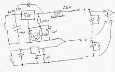
re that diagram in post 21.
the rectifiers are missing.
the 22k should be replaced by the zener not added in parallel.
The regulator uses the 1.25V drop between it's ref pin and output to regulate.
That then fixes the output voltage = Zener +1.25V.
You have added a protection diode across the reg, but omitted the second diode to discharge the 10uF cap.
That cap can usefully be increased upto 220uF with measurable improvement in regulation. Omitting the cap with a 317 reg reduces it's performance to worse than 780x regulator.
I suspect the 338 responds similarly.
woolly said:Reason for regulating - im hoping that if i drop the voltage, i will have some power in reserve for loud passages of music. I don't want a loud bass passage to effect the power to the treble amps.
I'm afraid that's not going to happen like that. What you would be better doing is just regulate the amp's supply.
Although there are those that say putting a reg in the supply will only make supply impedance higher, and it can create problems at high frequencies. Not to mention the waste heat and real estate. They say that you are better taking up the same amount of space and spending the same amount of money on making the transformer and caps bigger in the first place.
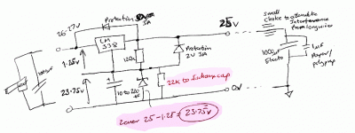
ok final design for today. I think i got it, and i have some real work to do!
Thinking the 22K can be kept to discharge the ref cap. It might speed up the response time for output fluctuation. The divider voltage gives 24.8V. Higher than 23.75V for zener, so Zener is still providing the reference.
don't take offense. I should check data sheets to confirm the 1.25V from ref to output.
Attachments
I think you have a good idea... but in the wrong place.... this is a class AB amp... and its supply has to be dynamic to be efficient. A class A amp on the otherhand wouldn't mind you regulateing christmass out of it... Andrew please correct me if I'm wrong....
There is a very subtle line on Pedja's site that says "he used to" dabble with the regulation thing... which I will construe as meaning he found other ways of improveing his designs...
I think T said, the Pedja regulator, GC and fet preamp combo is the best he has heard... I only have the preamp... head and sholders better than all the diy stuff I tried so far... only other pre I will likely still try is the Aikido, Which I have heard... but not in my system.
Nordic, I cannot correct you.Nordic said:I think you have a good idea... but in the wrong place.... this is a class AB amp... and its supply has to be dynamic to be efficient. A class A amp on the otherhand wouldn't mind you regulateing christmass out of it... Andrew please correct me if I'm wrong....
I don't have the competance to design a regulator for a power amplifier, whether ClassA or ClassAB or chipamp.
I recognise my limitations.
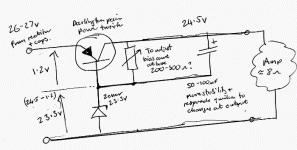
Had an idea for a new reg. this could be an insanity, it could be genius. Its certainly not tested. Based on capacitance multiplier. Note polarity of transistor. And the reference is now taken from the clean regulated side.
I have no plans at the moment to make it. Im going to forget the whole regulator thing for now, and finish other things.
If someone is looking to test a new idea- please feel free!!
I have no plans at the moment to make it. Im going to forget the whole regulator thing for now, and finish other things.
If someone is looking to test a new idea- please feel free!!
Attachments
hey, woolly
try this schem.
http://sound.westhost.com/project102.htm
it is basicly the same as above..
just change out the zenerdiode for one closer to what you want for output voltage.
and her is a tip for you:
put a diode(f.x. 1n4007) in series with the zenerdiode.
for the positive supply place catode to earth and anode to zenerdiode.
for the negative supply place catode to zenerdiode and anode to earth
this way we boosts the base voltage by 0.7volts.
her is an example if the zener voltage is 24 volts, the output voltage will be about 23.4volts due to emitter-base voltagedrop.
if we inserts an extra diode in the circuit we boosts the zener voltage and "eliminate" the transistors voltage drop.
e-mos - http://sound.westhost.com/project102.htm that looks perfect!! thank you. I knew there must be a simple way to do what i want!
AndrewT - think email is on now. divulge away
Ive been looking at National's help pages www.national.com/kbase/ and..
There are some "low drop out voltage" regulators that drop typ 1V. Not very powerful, normally for battery/portable devices. National have millions of regs, including the good compromise"Hybrids"
My aim is a "subtle" regulator..
1 to keep 4 seperate PSUs at the same nominal voltage
2 allow high current (equal to smoothing cap)
3 ideally keep some power in reserve for any sudden demand at one amp. I like the idea of that.
3 cheap simple easy to make
I think there is a solution. - just using good capacitors!
I think it was einstein who said "Make everything as simple as possible, but not simpler!
I was thinking a single transistor with opamp feedback was the way to go. Can be expensive for all parts x4. Now like the look of e-mos's Elliot Sounds suggestion. There are loads of useful wee projects there. Some are good.
- Status
- This old topic is closed. If you want to reopen this topic, contact a moderator using the "Report Post" button.
- Home
- Amplifiers
- Chip Amps
- power regulators