IVX said:BTW, if 85% efficiency, why so huge devices (e.g. my PCB 5.5"x5.5" at 95% efficiency)?
It's switched mode versus linear sine amplification. Your converter looks like a conventional PFC followed by a full bridge class-D stage with 4th-order output filter. How much continuous long-term output power can it provide in that size? My guess is 400W
Also, I think that both efficiency figures are too optimistic, the linear stuff shown some posts ago is likely to be 65-70% efficient, and your switched mode converter is likely to be 85-90% efficient at best due to the three high voltage switching stages working simultaneously with losses adding up (three 95% stages would give 85%).
Most rectifier systems use half wave center tapped or full wave bridge so the base frequency is actually 120Hz. Unfortunately most power amplifier supplies also use capacitor input ripple filters. This kind of input filter causes significant reduction in the rectifier conduction angle, often to as little as 5%(or even less). 5% of 8.3mS (the time for a 60 Hz half sine) ends up to be 2.4KHz the 40th(!) harmonic of 60 Hz. I think a little presence of 3rds and 5ths due to input sine wave distortion would be more easily cleaned up by the ripple filter than the 40th harmonic. This harmonic would be moved down in frequency by making the conduction angle larger.serengetiplains said:Hermanv, a harmonic = a non-60Hz frequency. Noise = a non-60Hz frequency. A harmonic = noise, give or take? Seems reasonable to me. Add to this the observation that Elgars (PS Audios, Accuphases) work and one has a basis for thinking, yes, you're probably missing something.
If you have a 100 Watt power amplifier, the power supply current will be about 5 Amps (I assumed an 8 Ohm load and 70% efficiency just for use as an example). With a full wave capacitor input filter and a 5% conduction angle the main rectifier diode current will be 100 Amps! Talk about a potential noise source! This is one reason that a large number of parallel filter capacitors work so much better than one big capacitor, the need to distribute that current spike.
For the example above a ripple filter of around 100,000uF would result in a 9 degree conduction angle or about 5%. That value of capacitor would not be unusual for that application.
I'm afraid I miss your point about the fact that Elgars (etc) work. I didn't say a pure sine wave was inherently bad; my point was that I believe low order odd harmonic distortion in this application wouldn't be bad either.
I didn't think that the ferro-resonant regulator with distortion was necessarily better than a pure sine regulator. I didn't think it would sound better, I mainly think it wouldn't sound any worse.
Buying a commercial power conditioner to put ahead of a commercial amplifier probably makes more sense to me that designing something as complex as your own power conditioner.
Building a high powered power line conditioner is probably pretty close in cost and effort to designing a high power audio amplifier.
Personally, my tendency would be to put all that effort into just making a better internal power source for the amplifier rather than trying to put a regulator ahead of the regulator if you see what I mean.
Absolutely constant input voltage is hardly a requirement for any well designed commercial power amp, I have personal doubts that the servo controlled variac or its’ variants does much of anything by itself to improve sound quality, Having said that, I agree that getting rid of EMI, spikes, transients and noise does have value. It's perfectly possible and simpler to accomplish that task inside the power amplifier itself.
I have read many performance reviews, there are two conclusions: 1. Adding a power conditioner improved the sound of a system. 2. Adding a power did not improve the sound of a system. Obviously the value of a power conditioner depends on two things, the quality of power you already have and the quality of the various regulators in the electronics you own.
Adding a dedicated power line to your house, converting the rectifiers in your amplifier to one of the newer technologies (a whole thread diyAudio Forums > Top >Amplifiers >Solid State >High Speed Diodes , is available) adding Ferrite cores to the power leads, being very careful in the choice of capacitors will probably get you more bang for the buck (I admit that a big Elgar for $100 is hard to beat).
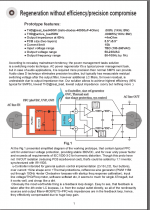
Our main aim was to make a 500w regenerator with outstanding precision that will suit most audio applications. Please note that our device provides 4mOhm output impedance at 50Hz, AFAIK there's no other regenerator with power range less than 10 kW which can it too. At moment the heatsink is a caraudio amplifier case housing, so 600W 230VAC in (1000W is ok too, if fan cooled chokes properly), 230VAC out, after 1 hour it gets 32C (at 25C ambient), RM10 chokes around 100mOhm and -10% inductance at 7A, all mosfets are about 100mOhm too, current limited at 15A, /\ edges are 50nS 100KHz, bodydiodes are SiC bypassed.
Overall efficiency at 500W 230VAC / 230VAC@25C seems to be little bit better than 95% mentioned, to be honest I have no power analyzer to say exactly. BTW, onsemi.com MC3***.pdf shows 98% for 230VAC at well old mosfets, we've used mosfets released during May 2006, so why should our losses be 50% higher? Whatsoever the efficiency we have made the best around regenerator (396W_230VAC_real_amp_load THD .008% 1KHz BW, 20KHz BW THD=.015%) 1-2Kg weight, extremely compact, and less then normal human body temperature at rated power. Of course we can reduce switching frequency to achieve better efficiency, our choice is a perfect sine, and minimal residual switching.
Actually, If anybody knows the field where we can use audio AC regenerator with several % of THD and 100% efficiency, any opinion will be highly appreciated, and why it's would be better then simple power cord?
Attachments
How do you bypass a 0.7V body diode with a 1.5V SiC diode without adding an additional schottky in series with the MOSFET and doubling conduction losses?
Also, how do you manage the high eddy current losses in inductor windings associated with center-leg gapped ferrites? This results in a dramatical and unexpected local heating of the turns near the gap.
Which overcurrent behaviour have you adopted? Shutdown? Peak current "chaotic" limiting? Linear "quiet" limiting?
How high are the idle losses?
Finally, I assume that you are using IPP60R099CS as switching devices.
BTW: I have been working on a similar commercial product with comparable impedance and distortion performance, but producing 120V 60Hz and up to 25A rms. It's almost finished now, but I can't disclose more details for the moment.
hermanv said:I agree that getting rid of EMI, spikes, transients and noise does have value. It's perfectly possible and simpler to accomplish that task inside the power amplifier itself.
Getting rid of that crud .... is a big job that, in my world, is not perfectly possible at all inside the amp---literally like trying to calm the glassy surface of a perfectly smooth lake back to its glassy surface (immediately!) after someone jumps into it. I've heard all the arguments that "that's the job of the power supply" and "shouldn't you be focussing on the DC side of things," etc. I've never heard a power supply do its DC job to perfection; see the latter part of my first sentence, so why not try to stop the person from jumping into the lake? Mind you, I'm a guy who prefers to experiment and allow results to sway my opinions.
serengetiplains said:Getting rid of that crud .... is a big job that, in my world, is not perfectly possible at all inside the amp---literally like trying to calm the glassy surface of a perfectly smooth lake back to its glassy surface (immediately!) after someone jumps into it.
Somehow an external circuit can calm the lake immediately, but not an internal one? I'm afraid that's too close to magic for me.
I have designed many power supplies, I'm not saying its easy to acheive very low noise leves, it requires a lot of speciallized knowledge.
The biggest single path for noise to get to the ouput is usually caused by the assumption that ground is ground. It just isn't at the performance levels needed to do this well. Magnetic, current and voltage sneak paths are common, careful design can eliminate all of them.
Of course the external solution can work just as well, if you're more comfortable doing it that way, it's perfectly OK. It just costs more.
Not sure if I can say more then already said, because PerfectSine is a commercial project. The pics given, was from the PerfectSine.pdf (one of early 2006 prototypes the only we can disclose here, i'll ask my employer to place web link on this .pdf, which no secrets at all), that we've presented to some worldwide AC conditioners/regenerators manufacturers. The nowaday proto has a sensible better specs. I've used very cheap ref.sine gen. at the ATmega8 u-con (11bit PWM out), and FFT's shows 73hz due to lowest THD of the ref.sine gen. at 73-74Hz exactly, so my measurement of the EMU1212M->380VDC_amp_EMU1212M is better. Even the cheap 16 bit DAC would noticeable improve the specs. I really don't see something interesting in the power stage or in the power conversion detail, all this things just a trivial SMPS task, actual worth is a feedback design, which continuously under upgrade.
BTW, we've 2 conversion stages -PFC ->380VAC_amp, and as my employer deleted isolation converter, that was presented at the very early versions, so 95% is not a problem (the amp idle power is 4.4W).
BTW, we've 2 conversion stages -PFC ->380VAC_amp, and as my employer deleted isolation converter, that was presented at the very early versions, so 95% is not a problem (the amp idle power is 4.4W).
Attachments
IVX said:i'll ask my employer to place web link on this .pdf, which no secrets at all
Ok, here it is.
http://gallery.audioart.kz/PerfectSine.pdf
Please note this is an early proto features dated as 2006/Jul we can now publish as we have even better specs/features now:
new feedback design and so on to be publish later.
I'm sure the technology licensing information would be availiable soon.
Regarding the PS Audio style of regeneration for say a CD player requiring +/- 15V would it not be possible to just generate the +/- 15V from an amplifier and power the circuit direct ?
Why use a transformer to step up the voltage to 120/240V only to have another transformer step it back down to +/- 15V ?
Why use a transformer to step up the voltage to 120/240V only to have another transformer step it back down to +/- 15V ?
Just a quick note on a first page misconception - the theoretical maximum efficiency of a linear amplifier driving a sine wave into a resistive load is 78.54%, not 70.7%. The power being produced is a sine^2 function . Doing the math reduces it down to PI/4 when operating at the cusp of clipping.
Cheers, Mark
Cheers, Mark
- Status
- This old topic is closed. If you want to reopen this topic, contact a moderator using the "Report Post" button.
- Home
- Amplifiers
- Power Supplies
- Power Line Conditioner