I found, that more bias results better sound. This is why I use balanced output. This means lower voltage, and higher current. I used source follower with 4A bias, but I lost some output devices 
Source follower means, that the source voltage follows the gate voltage. So if the gate voltage is 10V, and the source is 6V (4V bias voltage), and the gate goes up to 15V, the source will go up to 11V. Remember, the AC gain of this stage is aprox 1.
The gm depended by the bias. Higher bias means higher gm, and lower output impedance.
sajti
sajti said:I use this tube/mos balanced follower:
sajti
Sajti, FINALLY I see someone who uses the apparently long forgotten art of bootstrapping, sop that the triodes work into a current source! Looks like a great design to me!
ilimzn said:
Sajti, FINALLY I see someone who uses the apparently long forgotten art of bootstrapping, sop that the triodes work into a current source! Looks like a great design to me!
Thank You! I use this bootstrapping, because I want more gain, but I want to keep simple the overall design. Any other solution can results complicated amplifier without better parameters.
sajti
jeapel said:hi triode_al
"running at 1 amp and 25 volt is that it sucks details so the level sort of is uneven"
I run 26 volt 1.55 amp with irfp140 ccs and the sound
is very good i dont understand your point maybe more
explications")
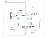
Here is the schema I use. It is the output that worries me. I like the simple way I use to 0-Vdc on the output and that at the same time settles the DC current in the output.
The 'sucking' of detail might come because I dont have enough 2SK135's - so one channel has a IRF230 (almost same Rout and similar Gm). So one channel is 2SK135/2SJ50 and the other IRF230/2SJ50. Would that give unbalance leading to a strange and physiological effect in the soundstage? Can anyone tell?
Attachments
triode_al said:
Driver stage used
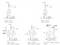
Here is the driver stage I used.
First I had R120, great warm sound. But with marked difference that the power really started after the volume is turned up. Driver = +17 or + 22 dB.
Then I had a 6N7 stage (driver +38 dB, with feedback from output reduced to total gain 20 dB, no ringing, great on the electrostats) but still the similar problem, but no warmth this time. Very detailed, sure.
The I switched to 6SN7 single and later to 6SN7 parallel (at +23 dB) and this is my last permutation with alower Rout (but not near 50 ohms).
Attachments
hi triode_al
I just see your schematic and:
-first it s not a single end source follower with current
source bias like all the discussion before
-it s a push pull follower so without feedback you need
very good complementary pair like 2sk135(N channel)
and 2sj50(P channel)
-have you many mosfet in parallel so what is the driver
zout
-in push pull maybe feedback from output to driver
would a good idea for the no complementary irf230
and maybe?? your high zout driver
Attachments
jeapel said:hi triode_al
-it s a push pull follower so without feedback you need
very good complementary pair like 2sk135(N channel)
and 2sj50(P channel)
-have you many mosfet in parallel so what is the driver
zout
-in push pull maybe feedback from output to driver
would a good idea for the no complementary irf230
and maybe?? your high zout driver
I agree that it is PP. Sorry, needed new thread.

But thanks for the characteristics. It does show that the two devices are not equal anyway, and as such, why have the same couple from the same supplier?
Just one set per channel.
I tried the feedback, but that sounded sort of fatging too.
I use ESL57 speakers, a nightmare for an amplifier, where the impedance falls very low.
This Mosfet output without feedback does give good high freq. On the scope too, a square wave stays OK with 4 ohms plus 0,5 mu even.
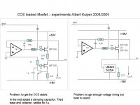
But I add the previous experiments with a true CCS, in the line Steve thought of when starting the thread..
I found out that even without a DC feedback with a 741, then the drift is minimal. Less than 20 mV. Even with the IRF150 which can dump a hell of a lot of current. So his idea is safe. Just that the negative rail in my case left too little voltage swing for my electrostats. You can drive such a thing into slipping fast!.
Attachments
hi it s not easy
for your test with ccs not stable:
-remove the .33 ohm you lost the damping factor (zout)
-remove the 1uF
-put a small .01uF directly on gate like me
www.loginnovation.com/jeapel
in my case the ccs was unstable but ok with .01uF or 10nF
for your test with ccs not stable:
-remove the .33 ohm you lost the damping factor (zout)
-remove the 1uF
-put a small .01uF directly on gate like me
www.loginnovation.com/jeapel
in my case the ccs was unstable but ok with .01uF or 10nF
Jeapel, I'll test.
Would the extra Zout be responsible for the assymetry in the up/downside (up being the slewed part) ;
or the Cgate?
As regards the latter: being a source follower just like thecathode follwer there is infinite Rin and ultimate low Cin-dynamically!
I'll try it out with the 10 nF stopper.
Would the extra Zout be responsible for the assymetry in the up/downside (up being the slewed part) ;
or the Cgate?
As regards the latter: being a source follower just like thecathode follwer there is infinite Rin and ultimate low Cin-dynamically!
I'll try it out with the 10 nF stopper.
- Status
- This old topic is closed. If you want to reopen this topic, contact a moderator using the "Report Post" button.
- Home
- Amplifiers
- Solid State
- Power follower class A Mosfet DC coupled.