Now I'm designing Power DAC like small Wadia. (Their PowerDAC was $80,000. it sounds GREAT but I'm not a rich)
You may will know PCM63P / PCM1704 well, this project is like huge PCM1704 / differencial driven.
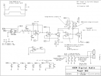
1. Principle
SPDIF to Right justified, 16bit signal
Serial to Parallel conversion
PCM to +(0000 to 7FFF), -(0000 to 7FFF) linear conversion
Voltage Reference (0 to 5V) works as volume control
Analog switch for Voltage Reference, driven by each data bit
Pre LPF after analog switch for each bit
+ side current source, MSB = 250mA, magnitude to LSB
- side current sink, MSB = -250mA, magnitude to LSB, +LSB offset
All Currents merged without any component - drives speaker directly.
2. Notes
Current amplifier can drive any "Low impedance speaker" but can't work with speaker's high impedance frequency area.
So it must have "impedance dumper" . it assures peak voltage < 4V.
register value for Current source will be 0.1%.
There can not be "Post LPF" like PCM1704, because added current drives speaker.
12dB Pre LPF are implemented for each bit.
3. Pros/Cons with PWM amplifier
Pros: Less signal modification. pure direct conversion from PCM to current.
Less Analog Component. there are no coil and capacitor at output terminal.
Cons: TOOOO low efficiency. implementation is nightmare.
now I understand why Wadia's PowerDAC had to be $80,000.
You may will know PCM63P / PCM1704 well, this project is like huge PCM1704 / differencial driven.
1. Principle
SPDIF to Right justified, 16bit signal
Serial to Parallel conversion
PCM to +(0000 to 7FFF), -(0000 to 7FFF) linear conversion
Voltage Reference (0 to 5V) works as volume control
Analog switch for Voltage Reference, driven by each data bit
Pre LPF after analog switch for each bit
+ side current source, MSB = 250mA, magnitude to LSB
- side current sink, MSB = -250mA, magnitude to LSB, +LSB offset
All Currents merged without any component - drives speaker directly.
2. Notes
Current amplifier can drive any "Low impedance speaker" but can't work with speaker's high impedance frequency area.
So it must have "impedance dumper" . it assures peak voltage < 4V.
register value for Current source will be 0.1%.
There can not be "Post LPF" like PCM1704, because added current drives speaker.
12dB Pre LPF are implemented for each bit.
3. Pros/Cons with PWM amplifier
Pros: Less signal modification. pure direct conversion from PCM to current.
Less Analog Component. there are no coil and capacitor at output terminal.
Cons: TOOOO low efficiency. implementation is nightmare.
now I understand why Wadia's PowerDAC had to be $80,000.
Attachments
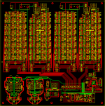
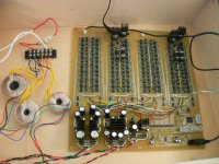
nightmare
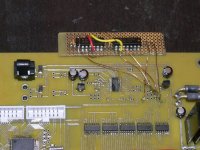
here is current board image.
it's 12x12 inches..
most left: Left D7 to D0 Current source / sink
2nd left: Left D14 to D8 Current source / sink
(right side as same)
Powers: for OpAmps, Transisters, 5V
DAI / Serial-Parralel / conversion for + and - / AVR / Voltage reference
100xOpamp, 400x0.1uF, 600 resistors, 60 analog switch, etc.
I'd like to ask you this project is value for the money about $600
Attachments
As far as I know the Wadia Power DAC consisted of 8 true 24bit PCM DACs per channel that worked phase-shifted to get 2.8 MHz without any noise-shaping. These DACs drove a minimalistic Class A power stage and volume control was entirely done in the digital domain.
Do we mean the same product?
P.S:
The term "full digital" refers to amps like TacT/Lyngdorf and the TI chips derived from it.
Do we mean the same product?
P.S:
The term "full digital" refers to amps like TacT/Lyngdorf and the TI chips derived from it.
like that you mention, only the idea of "current generator based" is like wadia. less bit, less sampling, leeeess power...
Instead better to say it is like discrete PCM63 or something?
anyway what I'm interested is another way of "full digital", multi bit PCM to curent conversion and direct speaker drive.
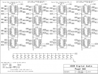
My DAC (then .. what is the best word to say ) has no oversampling, no noise-shaping, no PCM-PWM conversion, no post LPF, just using 31 circuit module to make 1 channel signal.
(If 24 bits and x4 phase shift, 188 circuits to make 1 signal!)
such a crazy can not be a commercial product. so must be DIYed
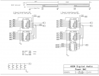
attached is more schematic, to make each signal bit from D15 - D0.
Instead better to say it is like discrete PCM63 or something?
anyway what I'm interested is another way of "full digital", multi bit PCM to curent conversion and direct speaker drive.
My DAC (then .. what is the best word to say
) has no oversampling, no noise-shaping, no PCM-PWM conversion, no post LPF, just using 31 circuit module to make 1 channel signal.(If 24 bits and x4 phase shift, 188 circuits to make 1 signal!)
such a crazy can not be a commercial product. so must be DIYed
attached is more schematic, to make each signal bit from D15 - D0.
Attachments
Jadis and Kondo had pure PCM no oversampling DACs, but with excessive analog filtering (valve-based). The other extreme is the Wadia Power DAC with only digital filtering. All the others (DIY kits excluded, I don`t know much about that field) have a combination of both.
Both Jadis and Kondo go other ways now. Jadis is using Analog Devices 12-bitters more common in labs than in hifi, still a bit closer to pure PCM than the 5-6 bit mainstream. I don`t know what Kondo is using. I am also not up to date what Wadia is doing now.
Both Jadis and Kondo go other ways now. Jadis is using Analog Devices 12-bitters more common in labs than in hifi, still a bit closer to pure PCM than the 5-6 bit mainstream. I don`t know what Kondo is using. I am also not up to date what Wadia is doing now.
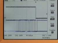
CS8416 Right Justified, 16 bit delay problem
Now I am working with board and having problem with CS8416.
(purchased last month, CS8416-CZZ)
Attached shows LRCK and SDATA with Right Justified, 16 bit configuration.
Last one bit of data is changing "1 clk after" LRCK edge.
//Serial Audio Format = (Right Justify 16bit)
//Bit 7:SOMS = 1, master mode
//Bit 6:SOSF = 0, 64Fs
//Bit 5:SORES1 = 1
//Bit 4:SORES0 = 0, 16 bit resolution
//Bit 3:SOJUST = 1, Right Justified
//Bit 2:SODEL = 0 not effected
//Bit 1:SOSPOL = 0, SCLK Polarity, rising
//Bit 0:SOLRPOL = 0, LRCK, high = Left
WriteData = 0xA8;
ret = I2CWrite(CS8416_ADDRESS, 0x05, &WriteData, 1);
Of course I tried 0b10000000 to 0b10111111 64 patterns, but could not get correct Right justified 16bit signal.
When SODEL = 1, the delay of SDATA is 2 clks
Does anyone see same issue?
Attachments
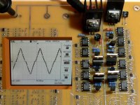
This soldering makes me crazy.
Now 3 bit implemented, it shows 500 Hz triangle wave.
can you see 7 step signal (by 3 bit upper/lower)?
It looks like R-2R DAC implementing, but this DAC can drive speaker.
Now I have dsPIC SD-I2S player, and direct sound converter, only by commodity devices. interesting.
Now 3 bit implemented, it shows 500 Hz triangle wave.
can you see 7 step signal (by 3 bit upper/lower)?
It looks like R-2R DAC implementing, but this DAC can drive speaker.
Now I have dsPIC SD-I2S player, and direct sound converter, only by commodity devices. interesting.
Attachments

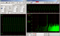
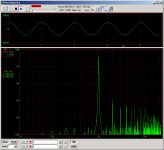
Loop back by Edirol UA-1 EX, digital out - Analog in at speaker terminal.
THD+N 2.2% is pretty bad, but anyway it's working.
with magnified view of received wav, I can see some gritch around negative peak. maybe one of lower current sink has trouble...
THD+N 2.2% is pretty bad, but anyway it's working.
with magnified view of received wav, I can see some gritch around negative peak. maybe one of lower current sink has trouble...
Attachments
Strange that there is no interest from others here. I can't offer any serious advice either being a newbie, but I like the idea and I would love to see how it develops. Keep it up!
Yea I'm interested too, though I really have nothing to add. It's a neat concept and I hope it pans out well.
I bet the PCB probably cost you big $$$ from express pcb...
nice work
Boris_The_Blade said:Yea I'm interested too, though I really have nothing to add.
Likewise. It's a very interesting and complicated project.
Thank you for interests.
After bit-by-bit measurement, re-soldering, bridge found! and cleaning, ... now all bit is working correct.
0.3% THD is not a fame as DAC
Now listening some musics.
nice. good at presentation of depth. musical enough.
best of the features is "interesting". only a pile of 74HCxx, 4580D, analog switch and TR/FET, C/R are driving speaker, from non tweaked PCM signal (and Reference Voltage, used for volume control).
Attachments
- Status
- This old topic is closed. If you want to reopen this topic, contact a moderator using the "Report Post" button.
- Home
- Amplifiers
- Class D
- Power DAC (like Wadia) full digital amp