Hi to all just one more question before turn this on.
Ok i was checking the trhead an found that you recomned matching the transistors, as usually i don't know what was that so i google it.
So my question would be what fets should i match(looks like all don't?), and what diference would i found whit and amp with matched fets and one without matched fets.
Does this works http://www.geofex.com/Article_Folders/fetmatch/fetmatch.gif
or is there a better way to do it that you whant to share?
anyway thanks a lot
Sorry my poor english
Hi,
you can use a simpler version without the opamp, but this one claims it is improved.
The 10k Rset should not be adjusted. It should stay fixed and an extra voltmeter across it to monitor Id would make setting up Vgs much easier.
I prefer, for mosFETs and BJTs, to put the current monitor in the drain/collector side (I use 2 resistors in series; a. to measure current and b. to adjust voltage levels). I have not measured Jfet yet.
vodoochild_Ar80 said:thanks Andrew,
i would like to know if is absolutely needed the matching cos' looks like im gonna need to buy lots of transistor until i found a pair, but of course if its good for the amp its good for me
AndrewT said:Hi,
there appears to be a benefit in matching transistors where they operate in parallel.
This happens in a long tail pair (LTP), current mirror & multi-pair output stage.
Some builders match Vbe/Vgs, others match gain/hFE/transconductance.
Like most things in life, matching transistors carries compromise. My suggestion is to buy say 10 of the low signal transistors and measure them for Hfe. Then choose pairs that are closest to each other. For the output FETs just buy the number you need for the total number of amp modules you intend to build and do the same (I measure for Vgs). Then choose adjacent doubles, triples or whatever and use these in groups.
The FET source resistors will help equalise load handling.
Cheers
Q

I'm interested in building this project. I've started reading this thread the other night and I'm not even halfway done. My initial feelings is that this amp is up to par.
Earlier this week, my work was throwing out a mess of old electronics, and they were nice enough to let me garbage pick. My coworkers think I'm nuts but that's ok. The electronics I picked up inlcuded the amplifier modules for a large shaker table (used for environmental testing). I'm almost done stripping out the good parts and getting ready to toss out the junk. This freebee from work yielded me 24 heatsinks (each measures 2x4x8 inches) and were used to hold 5 FETs. I also have about 2-3 pounds of IRF350's (and their pseudo equivalants). Some of the fets are ixtm21n50 by IXYS. Unfortunately the cases are TO-3. I also obtained a rather large transformer that is pretty much overkill for this project, it weighs about 60 lbs. I don't plan on using it for this, unless it's absolutely necessary.
Over this summer and fall, I'd like to build the 10 FET project, aka the nchan mos500, but I'm a bit unsure of what type of transformer I'll need. The IRF350 FETs are a little different than the mos500, so I'll assume that the power supply requirements are different. I'm open to making more power and/or lower ohm stability as I have plenty of FETs in my stockpile and heatsinks aren't an issue either. The only thing I need to pinpoint is transformer requirements. Any tips? Is there a simple calculation I can do to size it up myself?
Thanks in advance for your help!
tommyp
Hi Tommy,
the usual method of sizing a transformer for a ClassAB amplifier is 1 to 1.5times the output power. i.e. 100W requires 150VA.
Some commercial gear will use less than 1times and a few builders will use more than 1.5times. That choice is up to you but bigger does no harm (other than to your back when you move it).
Starting with an example.
100W into 8ohms requires 150VA 35-0-35Vac for a single channel.
Add in a second channel and you are upto 300VA.
Increase the loading to supply 4ohm speakers and it becomes 600VA.
If the output stage can supply sufficient current, then 2ohm loading requires 1.2kVA for a stereo amplifier. If you choose to use a 3times factor that 2ohm capable amp could use 2.4kVA 35-0-35Vac as it's transformer. The numbers get very big when you start looking at real currents into low impedance loads. That's the downside that most of the CAR amplifier power addicts fail to realise.
If you require a higher voltage then 40-0-40Vac or even 45-0-45Vac can be specified.
40Vac gives about 130W into 8ohms.
45Vac gives about 180W into 8ohms.
Greetings Tommyp
Looks like you've got a good find there. In my other thread "Brother of Quasi" I designed a board to take TO3 devices. The board was designed with a bi-polar transistor output stage in mind but it can be used with some minor modifications and some component changes to use TO3 mosfets.
In fact with 16 x IRF350's you could end up with very powerful stereo amplifier. If you have 16 x ixtm21n50's then you can build maybe the first Nmos700 but maybe I'm getting carried away.
This link takes you to the thread and also to a picture of that board next to the Nmos350.
http://www.diyaudio.com/forums/showthread.php?postid=1105657#post1105657
Let me know if you're interested and I can tell you about the modifications in detail.
Using Andrew's good guidance on transformer selection you will of course need a big one and filtered DC section to match.
Cheers
Quasi
Gents, Thanks for the tips. I rounded up some transformer information on the one I garbage picked, but to do so I had to garbage pick a second one! The specs are 2060 VA with multiple secondaries: 76.5-0-76.5, 92-0-92, 109-0-109 & 122-0-122. Packaged inside the chassis with each of the transformers are two Sprague 22000uF/100V caps. I supposed I could build a proof of concept Nmos700 (or more) in the future with this transformer. For now, I'll stick with a smaller Nmos type and I'll continue my parts collection for when its time to build. Right now, I'm building something else so amp building is a few months away.
quasi - I don't mind doing PWB design for this. The heatsinks I have dictate where the fets have to be placed, so I don't think the modded BJT layout will help me much. Thanks for the offer though.
According to the power matrix posted a few months back, there are number of FETs and power ratings listed and corresponding rail voltages. I assume that the table is based on the IRFP450s. Are voltage requirements for the IRF350 different than the IRFP450?
Thanks again from the noob
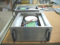
Pair of Monoblocks Under Construction
The attached photo shows a pair of monoblocks under construction. Right now only the power supply components are mounted. For this project I had the power transformers custom made by Plitron. These consist of 92VCT 625 VA devices which have been potted in a metal case. The potting serves to substantially reduce the acoustic signature the transformers. With no load, I had to press my ear against the case to hear any noise. Also, a metal case just looks nicer than a naked toroid. The transformers are rated at 625 VA at 50 or 60 Hz, which really means that at 60 Hz they should be capable of something closer to 700 VA. I'll test them once I get a large enough load resistor.
The filter cap bank consists of four 39,000 uF, 80V electrolytics. The green board on top of the caps is a mock-up made by gluing a 1x print of the PCB layout onto 1mm plywood. This method has proved very useful in ensuring that everything fits together mechanically before committing to build the PC boards.
In addition providing a convenient way of connecting the elec caps together, the board also contains ten 0.5 uf film caps across V+/Gnd and V-/Gnd. These caps should take care of any high frequency peaks the electrolytics may exhibit. High current connections are made either with ring terminals or via screw-down clamp terminal blocks. The PCB is a 2-sided design with PTH, allowing a doubling of the amount of copper in high current paths.
The aluminum angles provide a mounting surface for the ten TO3 devices per channel and also provide a mounting location for the output PCBs. The main PCB will mount vertically on the front panel, and a small PCB that controls turn-on relays, LED drive, etc. mounts on the rear panel.
Once the PC boards come back, I will finish drilling all the holes for the power devices, etc. Then all of the metal amp parts will be black anodized to match the aluminum handles.
The amplifier simulates at ~125W into 8 ohms, ~250W into 4 ohms, ~500W into 2 ohms. The amp will shut down if more than 50A peak is ever encountered, which could happen if full power were suddenly applied to a 1.25 ohm load, or if the outputs were shorted.
I'll post more information as it becomes available.
Attachments
Very impressive
Hi Analog_guy,
That is a very impressive setup indeed. Am I reading correctly, you are going to use a board with TO3 outputs? If so can we have a look?
My calcs using a 92v CT transformer indicate a power output of around 175 watts into 8 ohms (losses included).
Very impressive.
Cheers
Q
Hi Analog_guy,
That is a very impressive setup indeed. Am I reading correctly, you are going to use a board with TO3 outputs? If so can we have a look?
My calcs using a 92v CT transformer indicate a power output of around 175 watts into 8 ohms (losses included).
Very impressive.
Cheers
Q
Power Amplifier Under Development
Andrew,
If the amp goes into overload, it will certainly be audible, since the overload circuit acts as a circuit breaker and turns off drive to the output stage until the amp is power cycled. I chose this method to safeguard the two hundred dollars plus per channel in output devices. BTW, most switching power supplies rely upon a similar scheme.
Transients exceeding 50 amps could be accommodated either by increasing the number of output devices or by designing the overload sense circuit to more accurately take into account the transient overload tolerance of the output transistors. Adding more output devices is certainly a possibility, but incurs a capacitance penalty. I plan on using the BUZ901D/906D devices. They are rated at 16 amps per device continuous. (The output stage consists of four paralleled devices plus one BUZ901/906 acting as a predriver source follower.) Why 50 amps instead of 4x16=64? Because the overcurrent circuit has some built in tolerance, and I am a conservative designer by nature. If I could get transient overcurrent data from the manufacturer then I could tailor the overcurrent circuit to permit short term overcurrents exceeding the continuous current limit.
Regards.
Jeff
AndrewT said:Hi Analog,
if your amp is intended for 8ohm down to 2ohm speakers then it should be capable of driving a 1r0 resistive load. Certainly, it should not go into protection mode for 1r25. That is too restrictive and is likely to be audible with severe speakers.
Andrew,
If the amp goes into overload, it will certainly be audible, since the overload circuit acts as a circuit breaker and turns off drive to the output stage until the amp is power cycled. I chose this method to safeguard the two hundred dollars plus per channel in output devices. BTW, most switching power supplies rely upon a similar scheme.
Transients exceeding 50 amps could be accommodated either by increasing the number of output devices or by designing the overload sense circuit to more accurately take into account the transient overload tolerance of the output transistors. Adding more output devices is certainly a possibility, but incurs a capacitance penalty. I plan on using the BUZ901D/906D devices. They are rated at 16 amps per device continuous. (The output stage consists of four paralleled devices plus one BUZ901/906 acting as a predriver source follower.) Why 50 amps instead of 4x16=64? Because the overcurrent circuit has some built in tolerance, and I am a conservative designer by nature. If I could get transient overcurrent data from the manufacturer then I could tailor the overcurrent circuit to permit short term overcurrents exceeding the continuous current limit.
Regards.
Jeff
Monoblocks Under Construction
Yes, PC boards can actually carry a good deal of current based on the cross sectional area of the copper foil. For example, PC motherboards have on-board power regulators that deliver over 100A continuous at 1.5V to the CPU, and they use 1.0 Oz. copper. These boards are 2.0 Oz. copper, which is equivalent to approx 3 mils in thickness. Remember also that the continuous current is limited by the transformer to approx 7 amps.
By virtue of their fixed mechanical geometry, PC boards have the advantage of providing predictable values for such parameters as gate-drain coupling. For MOSFETs this is a key parameter bacause it affects high frequency stability. This is not the case for point-point wiring unless coax is used.
Once I get the boards designed, I'll post a layout.
Regarding the power output numbers, you are correct in your calculations regarding the max output power. However the power numbers I quoted are for distortion values at least 110 dB below the output level (20 Hz - 20 KHz). The last 20 percent of the supply voltage is where amplifiers start to see distortion increase.
Regards,
Jeff
quasi said:Hi Analog_guy,
That is a very impressive setup indeed. Am I reading correctly, you are going to use a board with TO3 outputs? If so can we have a look?
My calcs using a 92v CT transformer indicate a power output of around 175 watts into 8 ohms (losses included).
Very impressive.
Cheers
Q
Yes, PC boards can actually carry a good deal of current based on the cross sectional area of the copper foil. For example, PC motherboards have on-board power regulators that deliver over 100A continuous at 1.5V to the CPU, and they use 1.0 Oz. copper. These boards are 2.0 Oz. copper, which is equivalent to approx 3 mils in thickness. Remember also that the continuous current is limited by the transformer to approx 7 amps.
By virtue of their fixed mechanical geometry, PC boards have the advantage of providing predictable values for such parameters as gate-drain coupling. For MOSFETs this is a key parameter bacause it affects high frequency stability. This is not the case for point-point wiring unless coax is used.
Once I get the boards designed, I'll post a layout.
Regarding the power output numbers, you are correct in your calculations regarding the max output power. However the power numbers I quoted are for distortion values at least 110 dB below the output level (20 Hz - 20 KHz). The last 20 percent of the supply voltage is where amplifiers start to see distortion increase.
Regards,
Jeff
Hi to all i just wanted to know if the setup guide in the project pdf is also for the "nmos200".
Ho,and how big should be the heatsink if i run a -/+55 supply cos i saw a pic (page 14X) of quasi's amp and looked a litle tiny to me, to run on full power.
Ok promes to post a pic as soon as get back my cam (sometime this week).
thanks to all and sorry for my english
Ho,and how big should be the heatsink if i run a -/+55 supply cos i saw a pic (page 14X) of quasi's amp and looked a litle tiny to me, to run on full power.
Ok promes to post a pic as soon as get back my cam (sometime this week).
thanks to all and sorry for my english
Hi Juan,
The setup guide is the same for the Nmos200. For this amp I would set the bias current to about 60mA. Make sure you use resistors as specified in the setup guide. With 100 ohm resistors inserted in the fuse holders you should adjust until you see 6 volts across this resistor. When you swap this for the 10 ohm resistor re-ajust to get 0.6 volts.
The heatsinks I used in my amp measure 300mm x 80mm, plus the bottom is a sheet of 4mm aluminium and this connects to both heatsinks. Under heavy use the heatsinks do get a little warm but nothing to worry about. Heatsinks that size would be more than enough for an Nmos200 module or two.
Cheers
Q
- Home
- Amplifiers
- Solid State
- Power amp under development