AndrewT said:did you get my coil spreadsheet?
Andrew
I think I missed your spreadsheet. Could you please post it once more?
Thanks
Hari
Hi all
Here's yet another version of the pcb with a more toroidal coil for L1. It is made from 31 turns (20 turns in the first layer and 11 turns in the second layer) of 1.2mm (18AWG) wire on a 0.4" diameter spool. The height of the coil would be around 0.8". I've calculated the inductor using http://lalena.com/audio/calculator/inductor/
Hari
Attachments
hello,
Today I had a little time to play with my nmos350. I finally managed to install all the mos-fet's but the amp oscillates in a strange way. This phenomenon does not happend with only one pair.
The supply rails have +/- 70v unloaded and under a continuos 3A load they drop to about +/- 65. The bias current of the output stage is adjusted to 90 mA and the output dc voltage is 2mV.
I attached some oscilloscope plots, maybe you can help me with a hint about this problem.
Tommorow if I'll have a little time to play I will investigate the problem.
Thanks,
Daniel
Attachments
Oscillation
Hello Daniel,
from the waveform looks like you could have a power supply problem or too much inductance in your mosfet gate traces.
board layout may be a contributing factor here.
perhaps a filter network is needed to make up for this and kill the oscillation.
you could try a resistor of about 100ohm and cap of 22-39pF in series. placed between the gate drive leads after the gate stopper resistors. (tack solder it on to the track side of the board point to point. with some insulating tape underneath.)
See "fig 12" of Bob Cordell's mosfet power amp paper. "C8 & R52, C9& R53"
a couple of other things maybe to try first.
are the leads from your power supply to the amp short enough?
is the power supply bypassed with small value caps across the diode bridge, filter caps, and rails near the output stage, or any where leads/inductive effects or any are present.....?
hope this helps ?
-Dan.
Re: 2 pair version
Good question Loek. Actually they are of the same size but I used a larger footprint only to get the spacing for the tracks.
Hari
loek said:Shouldnot R23 have the same size as R24?
Maybe i missed something.
regards, Loek
Good question Loek. Actually they are of the same size but I used a larger footprint only to get the spacing for the tracks.
Hari
Oscillation
Hi Daniel (cd-i),
All the above from Dan (danieljw) plus make sure that all the FET gates have continuity via 27 ohm resistors to the driver transistors T9 and T10. Measure from the FET gate leg to the transistor leg.
Also check C4 on T6 or just replace it.
Replace or remove C3 and observe any difference. Then check the other capacitors.
What happens with just 2 pairs?
If none of the above works then you have a fault somewhere, either a component problem or track.
The Nmos350 is a very stable amp, so there is a genuine problem somewhere.
Cheers
Q
Re: Re: 2 pair version
Actually R24, R26 and R27 should be the same size as R23. This would suggest R24, R26 and R27 ended up becoming larger to span the rail track. I do not know why Hari needed to use a larger footprint part with the schematic drawing program rather than the same part and longer leads between the pads.
R23, R24, R26 and R27 are 0.5w resistors if my memory servers me correctly. That means R24, R26 and R27 should be the same size as R23 with the exception of longer leads to accomodate the longer distance between the pads.
Regards,
John L. Males
Willowdale, Ontario
Canada
24 July 2007 08:45
Official Quasi Thread Researcher
loek said:Shouldnot R23 have the same size as R24?
Maybe i missed something.
regards, Loek
jethari said:
Good question Loek. Actually they are of the same size but I used a larger footprint only to get the spacing for the tracks.
Hari
Actually R24, R26 and R27 should be the same size as R23. This would suggest R24, R26 and R27 ended up becoming larger to span the rail track. I do not know why Hari needed to use a larger footprint part with the schematic drawing program rather than the same part and longer leads between the pads.
R23, R24, R26 and R27 are 0.5w resistors if my memory servers me correctly. That means R24, R26 and R27 should be the same size as R23 with the exception of longer leads to accomodate the longer distance between the pads.
Regards,
John L. Males
Willowdale, Ontario
Canada
24 July 2007 08:45
Official Quasi Thread Researcher
Another in the making
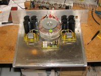
The father - son team are making progress.
Piccie of;
500va transformer, 2 x DC supplies with 20,000uF per rail each providing +/- 75 volt rails.
Shiny 3mm base blate with L bracket supports will be sanded to a nice brush finish.
Next job is to mount the heatsinks with the amp modules, power switch, nice blue LED, input sockets and speaker posts, fan etc.
Sticker on the transformer say's everything is ok!
Cheers
Q
Attachments
AndrewT said:well, put in dual pitch holes, so that builders can choose which footprint for easier to purchase power resistors.
The question of using dual pitch holes does not arise here due to the size of the track that the resistor has to span. In any case the resistor power rating cannot be ascertained from the size indicated on a pcb but from the actual schematics. The width of components in Protel is generic and generally assumed that a component of a certain length would also have a certain width. The pads are part of the foot print and cannot be separated. Hope this clears up any confusion regarding the size of components.
Thanks
Hari
Re: R23-24
Loek
I admit it can be misleading. Maybe I will create some footprints to cater for longer spacing and retain the same width. Protel does allow users to create their own footprints.
Hari
loek said:Indeed the powerrating is the same, i was misleaded by the outline drawing difference.
Loek
Loek
I admit it can be misleading. Maybe I will create some footprints to cater for longer spacing and retain the same width. Protel does allow users to create their own footprints.
Hari
NMOS350 problem
Hello Quasi and danieljw,
Today I didn't got any spare time to play with the amplifier (maybe tomorrow... )
)
But to clarify a little bit:
The pcb is the original one designed by quasi
All the components I used were brand new (that does not neccesarily mean that they are good).
the filter caps are bypassed with 100nF caps. The lenght of the power supply wires is about 20 cm and they are twisted together. The rectifier diodes on the bridge are not bypassed.
I believe it's a power supply problem because I noticed a strange behavior yesterday but I didn't had anymore time to investigate: the amp was running at low power levels and I unplugged the transformer. Almost instantly the oscillations were gone.
Anyway I will check the entire board again as soon as I'll got a little time.
Thanks for the tips guys
Daniel
Hello Quasi and danieljw,
Today I didn't got any spare time to play with the amplifier (maybe tomorrow...
)But to clarify a little bit:
The pcb is the original one designed by quasi
All the components I used were brand new (that does not neccesarily mean that they are good).
the filter caps are bypassed with 100nF caps. The lenght of the power supply wires is about 20 cm and they are twisted together. The rectifier diodes on the bridge are not bypassed.
I believe it's a power supply problem because I noticed a strange behavior yesterday but I didn't had anymore time to investigate: the amp was running at low power levels and I unplugged the transformer. Almost instantly the oscillations were gone.
Anyway I will check the entire board again as soon as I'll got a little time.
Thanks for the tips guys
Daniel
Re: NMOS350 problem
Can you tell us what the oscillation frequency is?
Cheers
cd-i said:Hello Quasi and danieljw,
Today I didn't got any spare time to play with the amplifier (maybe tomorrow...
But to clarify a little bit:
The pcb is the original one designed by quasi
All the components I used were brand new (that does not neccesarily mean that they are good).
the filter caps are bypassed with 100nF caps. The lenght of the power supply wires is about 20 cm and they are twisted together. The rectifier diodes on the bridge are not bypassed.
I believe it's a power supply problem because I noticed a strange behavior yesterday but I didn't had anymore time to investigate: the amp was running at low power levels and I unplugged the transformer. Almost instantly the oscillations were gone.
Anyway I will check the entire board again as soon as I'll got a little time.
Thanks for the tips guys
Daniel
Can you tell us what the oscillation frequency is?
Cheers
Re: Another in the making
Hi Quasi,
The father and son team is building the MOSFET or BiPilar version? I see amp modules in background of pic that is 4pair TO-3 module? Is this the same friend that has your NMOS-350? Are they building a BiPolar or MOSFET?
Regards,
John L. Males
24 July 2007 22:25
Willowdale, Ontario
Canada
Official Quasi Thread Researcher
quasi said:The father - son team are making progress.
Piccie of;
500va transformer, 2 x DC supplies with 20,000uF per rail each providing +/- 75 volt rails.
Shiny 3mm base blate with L bracket supports will be sanded to a nice brush finish.
Next job is to mount the heatsinks with the amp modules, power switch, nice blue LED, input sockets and speaker posts, fan etc.
Sticker on the transformer say's everything is ok!
Cheers
Q
Hi Quasi,
The father and son team is building the MOSFET or BiPilar version? I see amp modules in background of pic that is 4pair TO-3 module? Is this the same friend that has your NMOS-350? Are they building a BiPolar or MOSFET?
Regards,
John L. Males
24 July 2007 22:25
Willowdale, Ontario
Canada
Official Quasi Thread Researcher
"..................how do I connect the output of the power amp ..........without blowing up the sound card .............."
Simplest method is to get a 10 K potmeter . I use a 10 K , 10 turn Bourns pot for this . Start the pot from zero everytime you measure . However the safest method would be to build a battery powered buffer amp with an opamp ( OPA2134 ?) that will make sure you cannot blow up the input of the sound card.
Do a Google and you should come across such a circuit.
The 10 turn pot method is simple and safe if you are careful.
Cheers.
Re: NMOS350 problem
I removed the diode snubbers and the oscillation became much less but still there, sometimes.
The Zobel cap was the wrong type (Wima mkp 10 0.1/160) as supplied with the kit.
I replaced it with a cheap PES 0.1/160 and oscillation was gone. A few days later the amp blew up. Never got the chance to replace the RC snubbers. This was the end, after two months rebuilding this pair of amps repeatedly due to components blowing.
I set up a FET output amp (different type from this) using a PSU with RC snubbers across the rectifier diodes. It oscillated.cd-i said:Hello Quasi and danieljw,
Today I didn't got any spare time to play with the amplifier (maybe tomorrow...
But to clarify a little bit:
The pcb is the original one designed by quasi
All the components I used were brand new (that does not neccesarily mean that they are good).
the filter caps are bypassed with 100nF caps. The lenght of the power supply wires is about 20 cm and they are twisted together. The rectifier diodes on the bridge are not bypassed.
I believe it's a power supply problem because I noticed a strange behavior yesterday but I didn't had anymore time to investigate: the amp was running at low power levels and I unplugged the transformer. Almost instantly the oscillations were gone.
I removed the diode snubbers and the oscillation became much less but still there, sometimes.
The Zobel cap was the wrong type (Wima mkp 10 0.1/160) as supplied with the kit.
I replaced it with a cheap PES 0.1/160 and oscillation was gone. A few days later the amp blew up. Never got the chance to replace the RC snubbers. This was the end, after two months rebuilding this pair of amps repeatedly due to components blowing.
- Home
- Amplifiers
- Solid State
- Power amp under development