I had asked a couple of questions on this earlier, and have since looked into things a bit more, and hence more questions have arisen. Any input is much appreciated.
I'm looking at trying to shoe horn in the iron from the Heathkit AA-100 amp into Pete's design. Heathkit schematic here: http://www.tech-systems-labs.com/schematic/AA-100.JPG
On the output side things look OK, 7.8k primary, various taps on the secondary.
Power xfrmr is not a nice of a fit, but perhaps will work, my thoughts below:
Edcor 560 VCT B+ vs. Heathkit 720 VCT B+: figure I'll just knock down each leg of the B+ right off of the secondary, before it goes to the PCB to make the voltage friendlier for the caps.
6.3V Heaters, no problems.
Edcor 50-0-50 bias supply vs. Heathkit 0-50 V bias tap: take the 50V bias tap and the B+ CT into a FWB rectifier, output of that into R7, skipping D3 and D4.
Bring it up slow on the Variac and see where I'm at. Any flawed logic here?
Edcor 50-0-50 bias supply vs. Heathkit 0-50 V bias tap: take the 50V bias tap and the B+ CT into a FWB rectifier, output of that into R7, skipping D3 and D4.
That doesn't work, since the B+ CT is grounded. But no problem using a single 50V bias tap as opposed to the two on the Edcor. Just connect the single 50V tap to one of the two diodes, and leave the other unconnected. It makes a half wave rectifier, but it works fine - I was running a Hammond 300-series transformer that way before I got the custom Edcor.
Pete
Progress report, observations.
Here are a few photos Of my progress.
I cheated and had the top panel made by Schaeffer Ag (front panel express here in Europe).
I made a few changes from Pete's mechanical drawings.
The size of the IEC needs to be changed so that it is the same as the IEC in the BOM.
Pete's IEC has a lower profile, shame its not stocked by mouser.
This is the one in the BOM the connection is a little different too.
I moved the outboard screw holes so that the 0.5" frame is centered.
Q1 and Q2 are mounted with small heat sinks under main panel, hopefully between them they should prevent anything going pop.
Here with some tubes for motivation.
Still waiting to make contact with Edcor. Some caps are back ordered at mouser and U1 and U2 got forgotten so they are coming with the caps.
Here are a few photos Of my progress.
I cheated and had the top panel made by Schaeffer Ag (front panel express here in Europe).
An externally hosted image should be here but it was not working when we last tested it.
I made a few changes from Pete's mechanical drawings.
The size of the IEC needs to be changed so that it is the same as the IEC in the BOM.
Pete's IEC has a lower profile, shame its not stocked by mouser.
This is the one in the BOM the connection is a little different too.
An externally hosted image should be here but it was not working when we last tested it.
I moved the outboard screw holes so that the 0.5" frame is centered.
An externally hosted image should be here but it was not working when we last tested it.
Q1 and Q2 are mounted with small heat sinks under main panel, hopefully between them they should prevent anything going pop.
An externally hosted image should be here but it was not working when we last tested it.
Here with some tubes for motivation.
An externally hosted image should be here but it was not working when we last tested it.
[/URLStill waiting to make contact with Edcor. Some caps are back ordered at mouser and U1 and U2 got forgotten so they are coming with the caps.
That doesn't work, since the B+ CT is grounded. But no problem using a single 50V bias tap as opposed to the two on the Edcor. Just connect the single 50V tap to one of the two diodes, and leave the other unconnected. It makes a half wave rectifier, but it works fine - I was running a Hammond 300-series transformer that way before I got the custom Edcor.
Pete
Old ham radio trick for C- -- wire a filament transformer secondary to secondary of the extant filament transformer and pull the bias voltage off the new xfmr.
Alright. I had a *slap forhead* moment with regards to post #111. The 10uF caps, are used along the regulated power supply for 150v. So I would guess that a 200v cap would be sufficient unless the regulator shorts and the full B+ goes down the line. So 600v+ 10uF caps seem kinda silly now.
I picked up a Hammond 370HX for the job (for now) so I'll have to do the half-wave bias rectifier thing.
I picked up a Hammond 370HX for the job (for now) so I'll have to do the half-wave bias rectifier thing.
Last edited:
Progress
Decided not to use my existing iron, so will await the Edcor xfmrs-- sometime around Thanksgiving -- here's the progress to date:
Decided not to use my existing iron, so will await the Edcor xfmrs-- sometime around Thanksgiving -- here's the progress to date:
An externally hosted image should be here but it was not working when we last tested it.
I was poking around looking for cheap Novar sockets and I noticed that ESRC has extended the Summer $1 tubes sale. One tube is relevant to the DCPP.
Vacuum Tubes - Audio Tubes - ESRC Vacuum Tubes - Electron Tubes
Vacuum Tubes - Audio Tubes - ESRC Vacuum Tubes - Electron Tubes
Cute, stubby guys:
An externally hosted image should be here but it was not working when we last tested it.
My Edcor order arrived today.
Is there anybody else using 6JM6's?
Jeff
31JS6C for me...
Look man, no heater TX!cheers,
Douglas
Is there anybody else using 6JM6's?
I have a bunch or different tubes to try, but I don't think I have any 6JM6's. Initial experimentation will be with 6GV5's. They are on sale for $1 at ESRC and VacuumTubes.net, so I got 20 of them. I can "test" a few. After everything is working 6LR6's will be used for maximum power testing. I got 8 used ones cheap on Ebay. Some are pretty toasty looking. Bassically, if I have it, and it fits the socket, I'll try it.
and it fits the socket, I'll try it.
my sophomoric sense of humor is overcome by the necessity of good taste.
my sophomoric sense of humor is overcome by the necessity of good taste.
OK, I'll narrow the field a bit. If it's made of glass, glows, and fits in the socket, I'll try it. AND, for those who like to watch, I'll even take pictures!
I guess a somewhat compatible pinout might be a good idea too, but I have a big box full of "mystery tubes" that I have collected over the years. They have no numbers on them.
As with my other amplifier projects I will not populate any of the power supply components until last. I have several adjustable regulated bench supplies up to 650 volts at 1.7 amps. Enough to dial up some serious action. My main objective with this board is a learning experience. The 6GV5 looks an awful lot like a 6AV5 with a funny looking base and a plate cap. I also have about 25 different IF amp tubes to try with somewhat compatible pinouts including a few hundred 6CB6's.
The 6JN6s are in there now
Does this mean that your amp is up and running?
Since I returned from West Virginia I have been either at work, or working on the Simple P-P manual. I NEED A BREAK!
My birthday is in a few days so Sherri wanted to take me out to dinner and a movie or something. She said that it was my birthday so I really could do whatever I wanted, so instead of spending a day (and a whole bunch of money) out, I said that I would rather get away from the stresses of sitting in front of my computer or the computer at work, by.......building an amp (sort of). I have been looking at or photographing, green circuit boards for years. To really de-stress, I needed a change. OK, Saturday I decided I would build (in her words) the pretty red one!
I went over to the warehouse and grabbed some tubes. We have been having record heat so I could only stay there for a few minutes, so I just threw a hand full of used 6CB6's and all of the 12 pin sweep tubes that I could gather in about 10 minutes in a box.
I was originally planning to build the board as Pete intended without modification until I realized that some surgery would be needed to accomodate all of those different tubes. I did find 5 6JN6's so I still wanted to build the board such that it could be tested as it was designed before modification. Unfortunately I didn't have some of the parts, and this was to be a "one day project", so I was going to make do with what I could find.
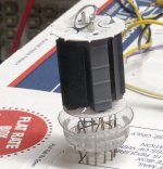
Saturdays build didn't go well at all. I had already soldered some black phenolic 12 pin sockets into the board because they were the only PC board sockets that I had. I tried to test fit a tube into one of the sockets. It refused to go in and I refused to give up. The stalemate resulted in a shattered tube and a bleeding hand. At least we will all get to see a teardown of a NOS Sylvania 6HF5 sweep tube. Sherri convinced me that this was not a de-stressing activity, so we retreated to the local sports pub to drink some beer and watch the Gators and Hurricanes win.
Sadurday evening in between passing out candy to the few kids left in the neighborhood, some more football, and some more beer, I gathered up my best guess of the parts needed to complete the build.
My birthday is in a few days so Sherri wanted to take me out to dinner and a movie or something. She said that it was my birthday so I really could do whatever I wanted, so instead of spending a day (and a whole bunch of money) out, I said that I would rather get away from the stresses of sitting in front of my computer or the computer at work, by.......building an amp (sort of). I have been looking at or photographing, green circuit boards for years. To really de-stress, I needed a change. OK, Saturday I decided I would build (in her words) the pretty red one!
I went over to the warehouse and grabbed some tubes. We have been having record heat so I could only stay there for a few minutes, so I just threw a hand full of used 6CB6's and all of the 12 pin sweep tubes that I could gather in about 10 minutes in a box.
I was originally planning to build the board as Pete intended without modification until I realized that some surgery would be needed to accomodate all of those different tubes. I did find 5 6JN6's so I still wanted to build the board such that it could be tested as it was designed before modification. Unfortunately I didn't have some of the parts, and this was to be a "one day project", so I was going to make do with what I could find.
Saturdays build didn't go well at all. I had already soldered some black phenolic 12 pin sockets into the board because they were the only PC board sockets that I had. I tried to test fit a tube into one of the sockets. It refused to go in and I refused to give up. The stalemate resulted in a shattered tube and a bleeding hand. At least we will all get to see a teardown of a NOS Sylvania 6HF5 sweep tube. Sherri convinced me that this was not a de-stressing activity, so we retreated to the local sports pub to drink some beer and watch the Gators and Hurricanes win.
Sadurday evening in between passing out candy to the few kids left in the neighborhood, some more football, and some more beer, I gathered up my best guess of the parts needed to complete the build.
Attachments
Sunday morning was spent in church, and the afternoon was spent in the pool, watching more football (hey the Dolphins won too), and soldering a few parts into Petes shiny red board. After grilling and eating some animal flesh, it was time. Time for what? Time to set the phasers on stun and flip the switch.
Stun? Yes, I must be getting old, but I set all of the power supplies to the voltages specified in Petes schematic. OK, I rounded 340 off to 350, but his paper clearly says 340 +/- 20%! I don't have any 8K ohm OPT's but I got boxex full of 6600 ohm OPT's so that is what I used.
OK, I put in the 6CB6's and attempted to test the circuit. It didn't work. No B+ to the driver tubes. Why, OOPS I forgot to put in the resistors that feed those tubes (R48 and R49). It then took 9 6CB6's to find 4 that I can get to balance. This may not be an issue with known good tubes.
Next, the 6JN6's. Again it didn't work on the first try, and again it was because I left out some more resistors. I must state that I modified the board a good bit and didn't exactly follow the prescribed parts list too well.
Now, with all of the tubes in their sockets, and the bias set to the prescribed 40 mA per tube it is time to crank it up. Using 6JN6's and a 6.6K ohm load I find that Petes estimate of 18 WPC was a bit conservative. I get 30.
I measure 30 WPC at 2.2 % distortion in one channel without GNFB, and 1.2 % distortion with GNFB. The other channel clips asymetrically which is caused by one wimpy output tube. I get 3.4% distortion at 30 watts without GNFB and 2.2% with GNFB in this channel. No attempt to optimize anything was made because my "one day project" is running out of time.
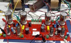
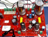
As I stated previously, I built this thing as a learning experience, and I intend to experiment on it a bunch at a later date. For this reason I built my board with all of the components on the same side as the tube sockets because it is easier to experiment on that way. I also cut a few runners, re routed a few things, and even drilled a few new holes. This was done to allow a wide variety of different tubes. I am posting a picture of my build, but don't try to use it as an example, and excuse my crude substitutions for the trimmer pots, these were all I could find.
Stun? Yes, I must be getting old, but I set all of the power supplies to the voltages specified in Petes schematic. OK, I rounded 340 off to 350, but his paper clearly says 340 +/- 20%! I don't have any 8K ohm OPT's but I got boxex full of 6600 ohm OPT's so that is what I used.
OK, I put in the 6CB6's and attempted to test the circuit. It didn't work. No B+ to the driver tubes. Why, OOPS I forgot to put in the resistors that feed those tubes (R48 and R49). It then took 9 6CB6's to find 4 that I can get to balance. This may not be an issue with known good tubes.
Next, the 6JN6's. Again it didn't work on the first try, and again it was because I left out some more resistors. I must state that I modified the board a good bit and didn't exactly follow the prescribed parts list too well.
Now, with all of the tubes in their sockets, and the bias set to the prescribed 40 mA per tube it is time to crank it up. Using 6JN6's and a 6.6K ohm load I find that Petes estimate of 18 WPC was a bit conservative. I get 30.
I measure 30 WPC at 2.2 % distortion in one channel without GNFB, and 1.2 % distortion with GNFB. The other channel clips asymetrically which is caused by one wimpy output tube. I get 3.4% distortion at 30 watts without GNFB and 2.2% with GNFB in this channel. No attempt to optimize anything was made because my "one day project" is running out of time.
As I stated previously, I built this thing as a learning experience, and I intend to experiment on it a bunch at a later date. For this reason I built my board with all of the components on the same side as the tube sockets because it is easier to experiment on that way. I also cut a few runners, re routed a few things, and even drilled a few new holes. This was done to allow a wide variety of different tubes. I am posting a picture of my build, but don't try to use it as an example, and excuse my crude substitutions for the trimmer pots, these were all I could find.
Attachments
Now what. I have an hour left in the evening, so there are two important things left to do. Crank up the power, and crank up the volume.
The amp looks so benign with a mere 350 volts, so I decided that 450 volts would be a good place to start. So, I set the phasers somewhere in between stun and kill and flipped the switch. There was no earth shattering kaboom, it just worked, I didn't even need to readjust the bias. Power was now 50 WPC at some ridiculous 1.05% distortion number. I decided that this was more than my speakers really like to eat, so I stopped here and connected the CD player and speakers up.
This thing ROCKS. The sound is very punchy and dynamic, as long as you unhook the GNFB. I tried music from mellow to metal, but in all cases I liked the sound better without the feedback. More experimentation will occur but this is a good sounding amp from the start. I haven't even turned any of the trimpots yet.
I plan to test several different output and driver tubes and find the best operating points for each one, but it won't happen until the Simple P-P is done.
Attachments
Does this mean that your amp is up and running?
Yes, out on a piece of plywood, with a couple of the UTC LS-54 output transformers; they're running the midbass-midrange-tweeter section of my speakers. Today was the day I was going to drop in 6LF6s and up the B+, but my boss decided that I should spend the day reworking budgets, so the amps just played music as-is. They rock very nicely.
- Home
- Amplifiers
- Tubes / Valves
- Posted new P-P power amp design