OK, I am finally employed again and I can at least start to think again about building one of these. I have read through the entire thread but it has been a while. I have some 6GV5 and 6GY5 tubes already. I have repaired a few tube amps, converted a Magnavox 196 to the RH84 circuit, and failed to fix an amp or two as well. I figure I can manage one of these with some help from the fine folks here. I would like to get more power than the stock build but still keep it sane. Would the CXPP60-MS-5K be a good choice, run at a little under 450V for about 50W? or maybe the 6.6K at a little over 450V?
Of course, if I stumble upon some 6HF5 tubes I'll probably want to build a 100W amp as well but I'll cross that bridge later.
Also, are there any Front Panel Express files floating around for a top plate for this amp?
Thanks,
Michael
Of course, if I stumble upon some 6HF5 tubes I'll probably want to build a 100W amp as well but I'll cross that bridge later.
Also, are there any Front Panel Express files floating around for a top plate for this amp?
Thanks,
Michael
Michael, I'm working on my version of this as well. I would suggest staying under 450 since that is the voltage rating on commonly available caps. You can find 500v ones, but harder and going above 500v is likely to mean moving caps off the board. Be mindful of turn on surge, too.
Also, are there any Front Panel Express files floating around for a top plate for this amp?
Will they accept "dxf" format? Pete's mechanical drawing file has the top plate layout.
jeff
Will they accept "dxf" format? Pete's mechanical drawing file has the top plate layout.
jeff
dxf files crash Front End Designer...or at least that one does. I am using a Linux box and also tried the Windows version in Wine.
No matter because NightAnole sent me some files in FPD's native format. Thanks NightAnole.
This is my version of a sweep tube amp using 6GV5's. Good little tube matched with 40 watt hammond iron 6.6k. Very similar to the big red board, but I based it on the Compactron tripple triode for the first and LPT stages. I'm not pushing over 30 watts (triode mode) so the iron is ample. I have another designed and part fabed using 6LB6's with 60 watt iron. With 600 V B+, George was able to get out 125+ watts/channel so the iron could be boosted to the 100 watt hammomds etc... not much of a price difference.
Attachments

Last edited:
My Version....
Hello all
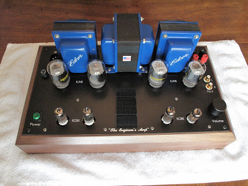
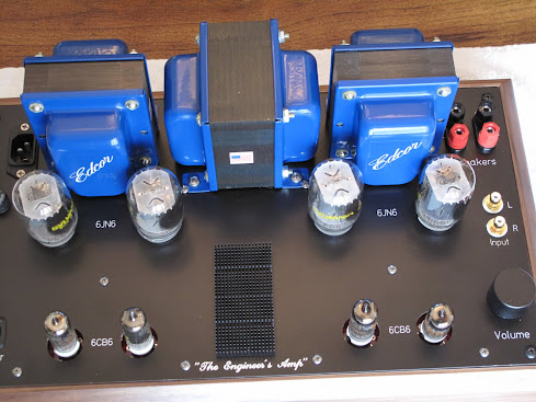
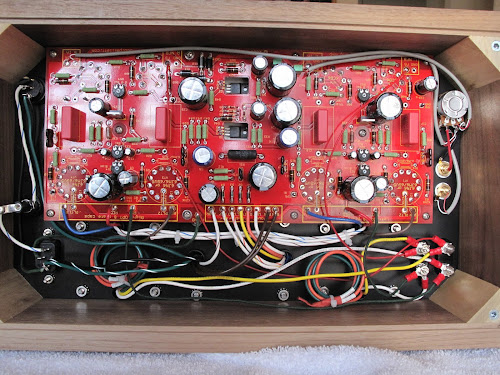
Here's my version: I built "stock" - using a Hammond walnut chassis, FPE top plate. I did break out the AC input and fuse - had parts on hand.
Note - when I took photos the feedback wires were wrong (corrected).
Things I would change:
1. Move power transformer slightly, relative to the main board - I had to nibble the transformer mounting base a bit to accommodate the screw for standoff.
2. Make the holes for preamp tubes smaller - if I build again will adjust FPE file accordingly.
Sound: fantastic with a pair of B&W's. Have also tried with vintage KLH's.
I'm using a vintage Marantz receiver as a preamp - also have tried a Hafler DH110. Both sound great and have good phono sections.
Link to album:
https://plus.google.com/photos/1003...ms/5640028731191986929?authkey=CNa9wKCq7qfCYg
Hello all
Here's my version: I built "stock" - using a Hammond walnut chassis, FPE top plate. I did break out the AC input and fuse - had parts on hand.
Note - when I took photos the feedback wires were wrong (corrected).
Things I would change:
1. Move power transformer slightly, relative to the main board - I had to nibble the transformer mounting base a bit to accommodate the screw for standoff.
2. Make the holes for preamp tubes smaller - if I build again will adjust FPE file accordingly.
Sound: fantastic with a pair of B&W's. Have also tried with vintage KLH's.
I'm using a vintage Marantz receiver as a preamp - also have tried a Hafler DH110. Both sound great and have good phono sections.
Link to album:
https://plus.google.com/photos/1003...ms/5640028731191986929?authkey=CNa9wKCq7qfCYg
OK, I am finally employed again and I can at least start to think again about building one of these.
Michael
I do have a set of transformers from a Knight KA95 integrated amplifier that was basically a 5-20. I am thinking of using the output transformers (6.6K) and if possible the power transformer also. The power transformer has HV secondaries of 435-0-435 and also 6.3-0-6.3 and 5-5 secondaries. Is there a way to use this effectively and bump the voltage down so I can use it safely with 450V caps?
Other options are to sell this iron and buy new Edcor -- either the whole set or just the power. My shoestring budget is a major consideration. Thoughts, pros, cons?
Thanks,
Michael
Last edited:
I would just replace the power transformer with a suitable one from Antek.I do have a set of transformers from a Knight KA95 integrated amplifier that was basically a 5-20. I am thinking of using the output transformers (6.6K) and if possible the power transformer also. The power transformer has HV secondaries of 435-0-435 and also 6.3-0-6.3 and 5-5 secondaries. Is there a way to use this effectively and bump the voltage down so I can use it safely with 450V caps?
Other options are to sell this iron and buy new Edcor -- either the whole set or just the power. My shoestring budget is a major consideration. Thoughts, pros, cons?
Thanks,
Michael
Thanks patkhan
By the way, I have a question: I had to rewire some things that doesn't appear in my picture to have my amp working as I wanted to. Basically on the picture my pilot lights are wired in parrallel on the relay outputs of the small remote PCB. They were dragging too much current and my relays wouldn't work. So I had to wire them directly onto the small 5-0-5v transformer I've added, trough the relays. For the NFB no problem as I had two spare contacts. But on the other one, which is wired in the picture so as to cut both 280v and 50V taps out of the xfmr, I had to remove the 50v taps and put my pilot lamp instead.
So now I have a relay that can switch the 280V on /off while the rest stays alive.
I was wondering if this could be harmful for the amp?
Hi All,
No answer so I should maybe rephrase the question
Is there a problem having a relay turning on and off the 280v supply to the red board, while the rest stays alive (50v and 6.3v) ?
This is how my board is wired so as to have a "standby function". For now I'm not really using it cause i'm not sure this is good for the amp...
As far as I understand the amp schematic, this means my Bias and heater voltages are staying alive while the B+ is shut down.
Please help!

I do have a set of transformers from a Knight KA95 integrated amplifier that was basically a 5-20. I am thinking of using the output transformers (6.6K) and if possible the power transformer also. The power transformer has HV secondaries of 435-0-435 and also 6.3-0-6.3 and 5-5 secondaries. Is there a way to use this effectively and bump the voltage down so I can use it safely with 450V caps?
Other options are to sell this iron and buy new Edcor -- either the whole set or just the power. My shoestring budget is a major consideration. Thoughts, pros, cons?
Thanks,
Michael
435 would be over 600v b+. If you have the choke of the gods you could choke load the power supply and get it down to 435. Another "trick" that i havent tryed is this:
get an old dual primary ac transformer (ones that do 110/220) and hook up one primary in series per output of the main transformer. So the hook up would be 435v out, into a primary, then the diode. George has used this in hte past, but i have not.
this means my Bias and heater voltages are staying alive while the B+ is shut down.
This is not a problem and is fairly common. I would not leave the amp in standby for long periods of time (days) because it can cause a degradation in the cathodes of the tubes. This was discovered in the early days of vacuum tube digital computers. The tubes were either conducting (a digital one) or cutoff (a digital zero). Tubes that wound up cutoff for long periods of time died faster than tubes that were full on a lot. Special cathode coatings were designed for this application and it is noted in their data sheets.
hook up one primary in series per output of the main transformer. So the hook up would be 435v out, into a primary, then the diode. George has used this in hte past, but i have not.
Not me. In fact I discourage this practice since the two primaries are often wound together with only the wire insulation seperating them. An insulation breakdown can create a path for line voltage into the secondary circuits, possibly causing a hot chassis condition. I have seen designs posted where this is done, especially with some toroid power transformers. I wouldn't use them.
Wiring a secondary in series with another secondary, or using a small toroid as a buck transformer to reduce the secondary voltage is a good and safe way to reduce the B+ voltage.
What would I do with these transformers???? I only have a Googled schematic to go on since I have never seen the actual amp.
The OPT's were used with EL34's in UL mode. They should be big enough for some power and decent sound. If they are over 5 pounds each, use them. Tape up the UL taps, they can't be used on a sweep tube amp.
The power transformer has no bias winding and produced 525 volts with tube rectifiers. It will produce nearly 600 volts with SS diodes and todays distorted high line voltage. OK, this amp works good with 600 volts or more on the plates of the output tubes. You just need to find a suitable source of power to run the board itself. The board will only see 350 volts or so so all the 450 volt caps are safe. This is the way I have built the last two amps.
The most obvious (but not the cheapest) solution is the Edcor transformer that Pete specified in the original build. The cheapest solution would be to use the Knight transformer for heater power and high B+ for the output tube plates only, and a small Antek for bias (50 VAC) with a medium sized Antek for board B+ (250 to 280 VAC). For coolness factor and lower B+ lift the dual 5AR4 circuit from the Knight power supply for the high B+.
I don't remember the numbers right now but somewhere in this thread I ran the 6GV5's at 500+ volts with a 6.6K load and got 80 to 100 WPC.
OK then. I think I'll not use the power transformer that I have. I have played with PSUD and am using it to half-arsed guestimate what secondaries I want to end up with around 450V B+. Am I right that it is around 360V?
If I understand correctly (and I may not) I need a power transformer that can manage about 400ma of high voltage and better than 6A at 6.3V, yes?
If this is correct then it looks like the Antek AS-4T360 would do?
That would be paired with an Edcor XPWR026-120 for bias supply (40-0-40 @ 20mA) with a value change in the bias supply filter to get -60V?
Sorting through all the Edcor offerings I'm not entirely certain which would be best -- would the XPWR143-120 do?
This is not a problem and is fairly common. I would not leave the amp in standby for long periods of time (days) because it can cause a degradation in the cathodes of the tubes. This was discovered in the early days of vacuum tube digital computers. The tubes were either conducting (a digital one) or cutoff (a digital zero). Tubes that wound up cutoff for long periods of time died faster than tubes that were full on a lot. Special cathode coatings were designed for this application and it is noted in their data sheets.
Thanks Tubelab
Mouser project list
I can share my saved Mouser project list for the 100 watt version of the Millett DCPP amp if anyone is interested.
I used 2 of these caps for the boost PS: JJ Can Capacitor 500µF / 500V Don't forget to also order the clamp.
I can share my saved Mouser project list for the 100 watt version of the Millett DCPP amp if anyone is interested.
I used 2 of these caps for the boost PS: JJ Can Capacitor 500µF / 500V Don't forget to also order the clamp.
I can share my saved Mouser project list for the 100 watt version of the Millett DCPP amp if anyone is interested.
I used 2 of these caps for the boost PS: JJ Can Capacitor 500µF / 500V Don't forget to also order the clamp.
scitizen17 - I finished soldering all the board components on and couldn't find a reasonably priced 600uf / 500v cap. I saw your post on using the 500uf so I did a search and found the cap at thetubstore. I wasn't sure it was the same one since I couldn't quite make out the logo on your pic, but thought how many black caps with red lettering could there be. Thanks for the verification. I should have waited 2 more days for you to post. Anyway I would be interested on looking at your project list to make sure I used correct parts. I had to make a couple of substitutions due to availability
scitizen17 - I finished soldering all the board components on and couldn't find a reasonably priced 600uf / 500v cap. I saw your post on using the 500uf so I did a search and found the cap at thetubstore. I wasn't sure it was the same one since I couldn't quite make out the logo on your pic, but thought how many black caps with red lettering could there be. Thanks for the verification. I should have waited 2 more days for you to post. Anyway I would be interested on looking at your project list to make sure I used correct parts. I had to make a couple of substitutions due to availability
Those JJ caps are the ones I used. Send a PM to me and I will forward the Mouser parts list.
It is important to note that if building the 100W version, R8, R9, R10, R11 should be changed to around 470R at 2 watt. Change R29, R30, R31, R47 to 220K-3W. If you wish, there is a 2000V 820 pF cap on Mouser for C7, C9, C10, C15: DEHR33D821KA3B Murata Ceramic Disc Capacitors
Check out this post if using 6HJ5: http://www.diyaudio.com/forums/tubes-valves/151206-posted-new-p-p-power-amp-design-35.html
If you look at the datasheet for the stock tube pin-out compared to the 6HJ5 it will be clear as to how it is to be connected if you refer to the Millett schematic.
Check out this post if using 6HJ5: http://www.diyaudio.com/forums/tubes-valves/151206-posted-new-p-p-power-amp-design-35.html
If you look at the datasheet for the stock tube pin-out compared to the 6HJ5 it will be clear as to how it is to be connected if you refer to the Millett schematic.
Last edited:
scitizen17 - sending PM. I like the chassis that you built. My metal working skills probably wouldn't be up to steel though. I think I am the only one using the coupling caps in the original BOM
George - my electronics parts supply for anything above 25 volts is kind of low.. mostly just digital level stuff. I have been nervous about the HV projects. I attended a tech school in the 80's and the rule was keep a hand in the pocket to keep the path of electricity from going across the heart. At that point I took the digital path. Your posts have been a great help in getting me going on this project. Also I have found your website very helpful.
Also does anyone know if the connectors that nic6paul used in post 712 are Molex two-screw barrier strips. I would like to try a couple of variations and wanted a easily reconfigurable setup
- Home
- Amplifiers
- Tubes / Valves
- Posted new P-P power amp design