Over on my forum I've been having some fun exploring why tapped horns sound so good, and in the process I stumbled across a subwoofer alignment that isn't used much by the DIY crowd.
In the interest of exploring it's benefits, I thought it would be fun to post our triple reflex bandpass designs.
Based on my experiments with it, it has some interesting features:
Pros:
Cons:
In the interest of exploring it's benefits, I thought it would be fun to post our triple reflex bandpass designs.
Based on my experiments with it, it has some interesting features:
Pros:
- It's possible to get absurdly low cutoffs with a triple reflex. In fact the biggest challenge I've had with these boxes is getting the F3 *high* enough, not low enough!
- Like all bandpass boxes, the vents roll off distortion. Triple reflex boxes do it to a greater extent than single or dual reflex. I do not like the nomenclature of calling these "eight order bandpass" because the rolloff isn't always eight order; it could be as shallow as fourth order.
- Because triple reflex boxes have three excursion dips, you can get absurd power handling. I'll post a design for an eight with an F3 of 15hz and 1000 watts of power handling. (out of an eight!)
- If your goal is a little bit more down to earth, you could probably get some deep bass out of small cheap woofers (like Bose did
") )
)
Cons:
- This is a hideously complex design. I am still trying to wrap my brain around it, and it seems that changing one variable affects all the others. For instance, if you change the tuning frequency of one port, it affects the other two ports as well.
- Don't even THINK about building one of these without a woofer tester. Bose stopped making these, and I'll be it's because even a bit of a drift in the QTS of the woofer will change the frequency response in a big way.
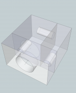
Here's a triple reflex with a single eight that can do one thousand watts without running out of displacement*, with an F3 of 18hz.
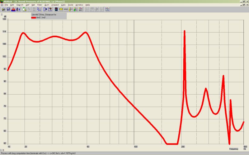
Frequency response of the sub. We get about an octave and a half of bandwidth.
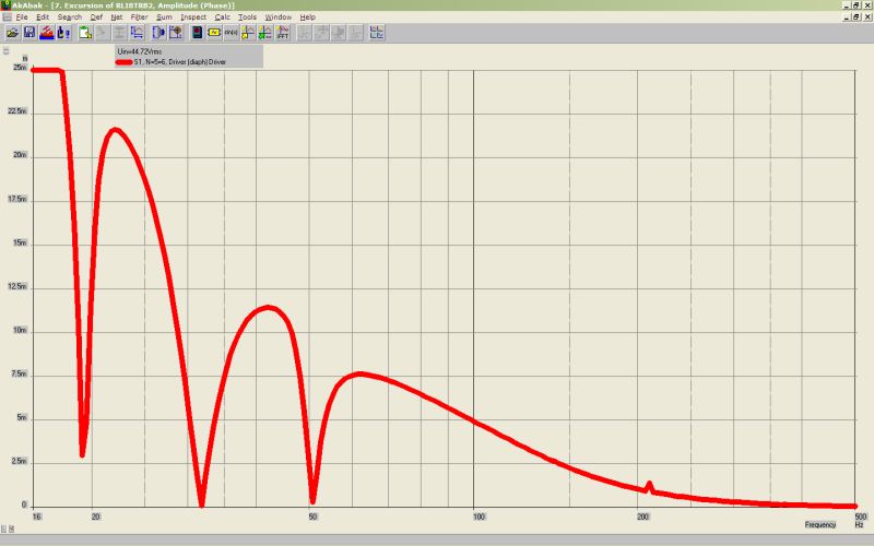
Here's the excursion. Due to the three dips in excursion due to the three tunings, we can handle over a thousand watts with a single eight. (* two ohm load - I designed this for the car where 2ohm is where amps deliver their maximum output.)

The group delay of the sub.
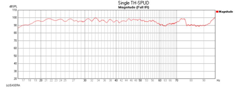
For comparison's sake, here's the Danley TH-Spud. F3 is about the same, but the TH-Spud has higher efficiency because it's bigger and it has twice as many woofers. The TH-Spud also has wider bandwidth. I think the triple reflex bandpass is a good option when you don't have the space for a tapped horn. Folding a tapped horn can be time consuming also.
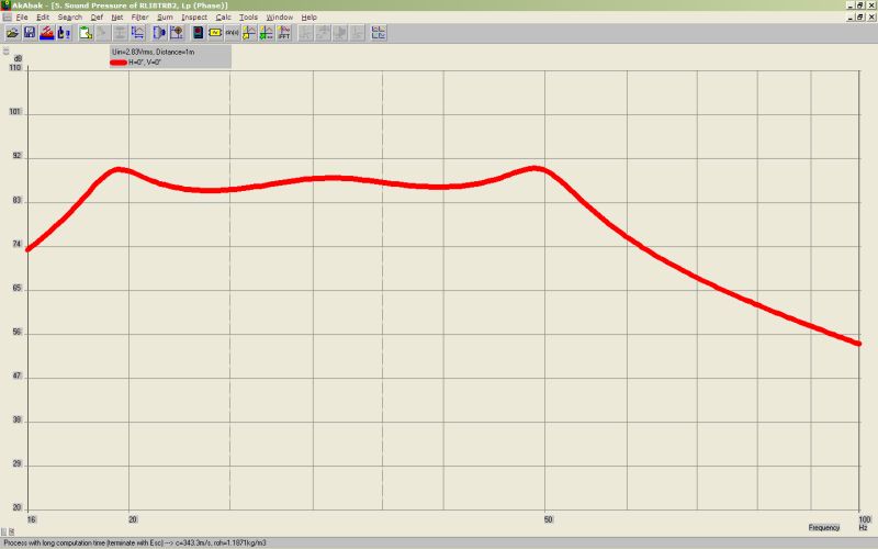
Frequency response of the triple reflex using the same scale as the TH-Spud.
Frequency response of the sub. We get about an octave and a half of bandwidth.
Here's the excursion. Due to the three dips in excursion due to the three tunings, we can handle over a thousand watts with a single eight. (* two ohm load - I designed this for the car where 2ohm is where amps deliver their maximum output.)
The group delay of the sub.
For comparison's sake, here's the Danley TH-Spud. F3 is about the same, but the TH-Spud has higher efficiency because it's bigger and it has twice as many woofers. The TH-Spud also has wider bandwidth. I think the triple reflex bandpass is a good option when you don't have the space for a tapped horn. Folding a tapped horn can be time consuming also.
Frequency response of the triple reflex using the same scale as the TH-Spud.
An externally hosted image should be here but it was not working when we last tested it.
Here's the Akabak script I used to make the sub. Note that the port on the third chamber is flared, just like the Bose subwoofer.
System 'S1'
|================================================= ================================================== =====
|REQUIRED AKABAK SETTINGS:
|File > Preferences > Physical system constants:
|Sound velocity c = 344m/s
|Medium density rho = 1.205kg/m3
|Sum > Acoustic power:
|Frequency range = 10Hz to 20kHz
|Points = 533
|Input voltage = 2.83V rms
|Integration = 2Pi-sr
|Integration steps = 1 degree ... 1 degree
|Integration method = Cross
|================================================= ================================================== =====
Def_Const |Hornresp Input Parameter Values
{
|Length, area and volume values converted to metres, square metres and cubic metres:
S1 = 248.22e-4; |Main Port Throat Area (sq cm)
S2 = 182.37e-4; |Area of main port tube (area betweent the flares)
S3 = 248.22e-4; |Main Port Mouth Area (sq cm)
L12 = 2.54e-2; |Main port segment 1 axial length (cm)
L23 = 50.0e-2; |Main port segment 2 axial length (cm)
L34 = 2.54e-2; |Main port segment 3 axial length (cm)
Vrc = 31.0e-3; |Rear chamber volume (litres)
Lrc = 22.5e-2; |Rear chamber average length (cm)
Ap = 45.6e-4; |Rear port cross-sectional area (sq cm)
Lpt = 82.6e-2; |Rear port tube length (cm)
Vtc = 14.16e-3; |Front chamber volume (cc)
Atc = 550.00e-4; |Front chamber cross-sectional area (sq cm)
Ata = 45.6e-4; |Front port cross-sectional area (sq cm)
Tpt = 46.07e-02; |Front port tube length (cm)
V3c = 85.44e-3; |Third chamber volume (litres)
L3c = 30.0e-2; |Third chamber average length (cm)
|Parameter Conversions:
Sd = 200.00e-4; |Diaphragm area (sq cm)
Arc = Vrc / Lrc;
Ltc = Vtc / Atc;
A3c = V3c / L3c;
}
|================================================= ================================================== =====
|Network node numbers for this horn-loaded vented-box system:
|0-Voltage-1-Resistance-2
| |
| 3-Chamber-4-Driver-5-Chamber-7-Port-12-Chamber-8-Segment-9-Segment-10-Segment-11-Radiator(1)
| |
| --------Port--------------------------
|================================================= ================================================== =====
Def_Driver 'Driver'
Sd=200.00cm2
Bl=18.30Tm
Cms=3.85E-04m/N
Rms=5.68Ns/m
fs=28.90Hz |Mmd = 74.30g not recognised by AkAbak, fs calculated and used instead
Le=2.90mH
Re=7.40ohm
ExpoLe=1
Driver Def='Driver''Driver'
Node=4=0=5=6
Coil 'L1'
Node=1=4
L=4mH
Rs=0.35ohm
Duct 'Rear Chamber'
Node=5=7
SD={Arc}
Len={Lrc}
Visc=0
Duct 'Front chamber'
Node=6=8
SD={Atc}
Len={Ltc}
Visc=0
Duct 'Third chamber'
Node=11=12
SD={A3c}
Len={L3c}
Visc=0
Duct 'Front Port'
Node=8=11
SD={Ata}
Len={Tpt}
Visc=0
Duct 'Rear Port'
Node=7=11
SD={Ap}
Len={Lpt}
Visc=0
Waveguide 'Main Port Segment 1'
Node=13=12
STh={S2}
SMo={S1}
Len={L12}
Conical
Duct 'Main Port Segment 2'
Node=13=14
SD={S2}
Len={L23}
Visc=0
Waveguide 'Main Port Segment 3'
Node=14=15
STh={S2}
SMo={S3}
Len={L34}
Conical
Radiator 'Horn mouth'
Node=15
SD={S3}
IMO 8th order bandpass = looks like a good way to destroy drivers
While the sim suggests that the driver can absorb 1000W before excursion limit is reached, think about what's going to happen when an 8" driver is hit with 1000W. Even 500 W. Hell, even 250 W. T/S params will shift, and the alignment no longer matches the nice Akabak predictions. Then of course there's the nonlinear effects of three vents tuned to different frequencies that are going to mess things up too.
While the sim suggests that the driver can absorb 1000W before excursion limit is reached, think about what's going to happen when an 8" driver is hit with 1000W. Even 500 W. Hell, even 250 W. T/S params will shift, and the alignment no longer matches the nice Akabak predictions. Then of course there's the nonlinear effects of three vents tuned to different frequencies that are going to mess things up too.
Most woofers can handle very high peak music power inputs, especially for transients only.IMO 8th order bandpass = looks like a good way to destroy drivers
While the sim suggests that the driver can absorb 1000W before excursion limit is reached, think about what's going to happen when an 8" driver is hit with 1000W. Even 500 W. Hell, even 250 W. T/S params will shift, and the alignment no longer matches the nice Akabak predictions. Then of course there's the nonlinear effects of three vents tuned to different frequencies that are going to mess things up too.
As far as "non-linear effects" go, well, I would assume that all the graphs show the response AFTER taking into account the tuning... that's what the math is for, right?
Most woofers can handle very high peak music power inputs, especially for transients only.
As far as "non-linear effects" go, well, I would assume that all the graphs show the response AFTER taking into account the tuning... that's what the math is for, right?
Wrong.
Most t/s param-based modelling tools model the response to small signals.
E.g. 1W or less.
1kW does not count as a "small signal".
<snip>
Cons:
- This is a hideously complex design. I am still trying to wrap my brain around it, and it seems that changing one variable affects all the others. For instance, if you change the tuning frequency of one port, it affects the other two ports as well.
- Don't even THINK about building one of these without a woofer tester. Bose stopped making these, and I'll be it's because even a bit of a drift in the QTS of the woofer will change the frequency response in a big way.
Yeah, I am looking into oddball enclosure arrangements ATM and a weakness that many have is a serious dependency on EXACT driver, enclosure and port specification.
Modelling these kinds of enclosures is tricky enough, but prototyping them can be a nightmare! Effective lengths of ports vs physical length, end corrections, tiny air leaks, even changes in enclosure volume due to driver displacement(!), plus many other factors, conspire against the tireless investigator.
Most manufacturers, rightly, can't justify the required substantial R+D for a system that probably won't work for the next batch of drivers they buy-in.
This leaves the field for those companies (eg. Blose) who can finance the R+D, and demand and get the requisite component parameter stability.
And, of course, the enthusiastic DIYer.
The results achievable from some of the more obscure enclosure design techniques are truly amazing and I would not discourage anyone from trying anything. Put saw to wood. Make stuff. That's what we do.
The reasons why commercial outfits don't use some of this tech has little to do with the quality of results, and more to do with the realities of operating a business that has to make LOTS of speakers that all sound the same, usually using components with a fair spread of parameters.
Some oddball ideas are just crap, hampered by fundamental flaws that mean they will never work, or by the originators poor grasp of physics or math. Others are ingenious and very amenable to the stroking of a delicate DIY hand. Yet others are rediscoveries of principles that just got forgotten in the whirlwind surrounding the publication of Thiele and Small's papers.
Anyway, did you build one? How did it sound?
I've had a hankering to try building one of these for years. I plan to use PR's instead of ports in an effort to keep the size down and to allow some degree of fine tuning in a much easier manner than hacking at ports. It still won't be an easy build. Does anyone have info or data from actual builds of this type?
Btw there was a freeware enclosure simulation program called SubwooferSimulator or SubSim that would handle these enclosures. It was much easier than Akabak if the learning curve for that program is daunting and a decent little program with some nifty features.
Btw there was a freeware enclosure simulation program called SubwooferSimulator or SubSim that would handle these enclosures. It was much easier than Akabak if the learning curve for that program is daunting and a decent little program with some nifty features.
Do you think you could post your forum address, please? Maybe add it to your signature.
it's forum.audiopsychosis.com
i'd put it in my sig but i don't want to spam unnecessarily, out of respect for the owners of the other forums I'm on
Yeah, I am looking into oddball enclosure arrangements ATM and a weakness that many have is a serious dependency on EXACT driver, enclosure and port specification.
Modelling these kinds of enclosures is tricky enough, but prototyping them can be a nightmare! Effective lengths of ports vs physical length, end corrections, tiny air leaks, even changes in enclosure volume due to driver displacement(!), plus many other factors, conspire against the tireless investigator.
Most manufacturers, rightly, can't justify the required substantial R+D for a system that probably won't work for the next batch of drivers they buy-in.
This leaves the field for those companies (eg. Blose) who can finance the R+D, and demand and get the requisite component parameter stability.
And, of course, the enthusiastic DIYer.
The results achievable from some of the more obscure enclosure design techniques are truly amazing and I would not discourage anyone from trying anything. Put saw to wood. Make stuff. That's what we do.
The reasons why commercial outfits don't use some of this tech has little to do with the quality of results, and more to do with the realities of operating a business that has to make LOTS of speakers that all sound the same, usually using components with a fair spread of parameters.
Some oddball ideas are just crap, hampered by fundamental flaws that mean they will never work, or by the originators poor grasp of physics or math. Others are ingenious and very amenable to the stroking of a delicate DIY hand. Yet others are rediscoveries of principles that just got forgotten in the whirlwind surrounding the publication of Thiele and Small's papers.
Anyway, did you build one? How did it sound?
I've been screwing around with the akabak model, and I've come up with something which seems to address the shortcomings of the triple reflex.
But first, a bit of background...
An externally hosted image should be here but it was not working when we last tested it.
This is the old Acoustimass sub. This is a triple reflex bandpass. I think this dates back to the 80s. As I see it, the advantage of a triple reflex is reduced distortion, very high efficiency, and best of all, low excursion. The triple reflex basically allows you to generate a lot of output from low-excursion drivers, and you can use cheap ones because the box filters out distortion. The downside is that it's hideously complex, and the transient response sucks.

This is a newer version. This is a really wild design - it is both a triple reflex AND a single reflex in the same enclosure. I don't even know what to make of this. Why did Bose add a third woofer? Perhaps to augment the last octave?

This is the current version. I did some screwing around with the triple reflex in Akabak, and I think I have an idea why Bose switched over to what *appears* to be a simple transmission line. (it's not)
Will explain in the next post...
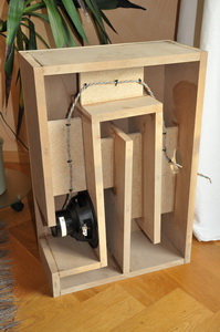
Last night I came up with an Akabak model which seems to address many of the short comings of the triple reflex bandpass. What you do is take the two rear chambers of a triple-reflex and replace them with a tapped horn. The front chamber (the big one) remains.
Picture Volvotreter's tapped horn, but with a coupling chamber in front, and you get the idea.
This has a series of advantages. First, it is very very difficult to get the three ports in a triple reflex to "play nice" because their dimensions are all connected. In other words, if you modify the length of one port, it affects the tuning frequency of the other two. The same applies to the volume of the chambers. They're all connected.
A tapped horn is quite similar to a simple vented box, but the volume of air in the box and the volume of air in the port is the same. The subwoofer is basically IN the port.
That's why we can replace two of the chambers in a triple reflex with a tapped horn.
This reduces the complexity of the design.
Transient response is improved because a tapped horn is a quarter wave resonator.
An externally hosted image should be here but it was not working when we last tested it.
The current acoustimass module is fairly similar to this. It *appears* to be a simple transmission line, but it's not. By mounting the woofers downward, the volume of air in front of the woofers forms a coupling chamber, and that coupling chamber rolls off high frequencies the same way that the front chamber in a triple reflex does.
"Slot loading" the woofers also lowers the F3 by raising the FS and the QTS of the woofer. I don't think there are any programs which can simulate this. But you can see it easily, just measure the Thiele small of a woofer when it's mounted an inch away from a wood floor, and you'll see that the T/S parameters change. For Bose, this allows them to get low bass out of small woofers.
I will post the Akabak model once I get the kinks out. The results are really quite nice. The coupling chamber in front does a nice job of filtering out the high frequency garbage, and that reduces distortion. The coupling chamber also increases efficiency (good ol' Hoffman's Iron Law at work.)
Last edited:
seen a triple reflex at a car dBL drag race.
i did not like it to be honest.
Generaly as one increases the order of the aligment the transient response gets worse, and sound gets more and more muddy.
If i need a lot of power from a small box i still prefer d.c. ported isobarics.
Surely that has its own disadvantages, and is not a usual design, but at least it is more or less predictable.
Allso, in designs You have more ports with more and more harmonics.
There are many reasons why this model was never a popular one.
Actualy the multi chamber vented designs was getting attention here, extending the usual dual chaber vented to have triple chambers, but it was not bandpass.
Suffered from same problems, even drivers aging effect on parameters resulted audible -by avarage human- differences.
This is a newer version. This is a really wild design - it is both a triple reflex AND a single reflex in the same enclosure. I don't even know what to make of this. Why did Bose add a third woofer? Perhaps to augment the last octave?
Perhaps that's the HT version, and the third woofer is what the center channel was connected to.
How about this route?
I tried an Akabak model of something similar to that. A single reflex bandpass, but instead of a single chamber, there's two chambers in front of the woofer.
Similar to the dual chamber reflex that's documented by Weems, and is also on Brian Steele's page. (diysubwoofers.org)
I couldn't get it to perform as expected; I think the problem is that with modern woofers, the port sizes get so huge that they actually swamp the volume of air in the coupling chamber. And when this happens, it gets very difficult to tune the ports.
It's a bit of a crapshoot.
I think this is one of the reasons the tapped horns work so well, the port and the coupling chamber are basically the same thing.
The best results I could come up with were a tapped horn feeding a coupling chamber.
~15 years back I had built a Weems type box for a single JL 8W6, it was a little beast.
***
I'm sort of curious about the dual reflex front chamber you were working on, what were your expectations? I would think the series tuned ports would drag the tuning down quite low considering you are working with the entire volume of the enclosure. And I would think to get the tuning up high enough there would be too much overlap.
This is a newer version. This is a really wild design - it is both a triple reflex AND a single reflex in the same enclosure. I don't even know what to make of this. Why did Bose add a third woofer? Perhaps to augment the last octave?
I would think the opposite: the third woofer is there to extend the bin's BW upwards! Remember that the Bose midbass bins are playing up to 200Hz or more. One would expect that a natural consequence of extending LF extension is a reduction in overall usable BW. The third woofer might help.
One would have to see the crossover, though. I wouldn't be surprised if there's a (or an extra) highpass on that orphan woofer.
- Status
- This old topic is closed. If you want to reopen this topic, contact a moderator using the "Report Post" button.
- Home
- Loudspeakers
- Subwoofers
- Post Your Triple Reflex Bandpass Designs