What enclosure did you use? It is very nicely arranged.based on Ljm L12-2 CFA Amplifier
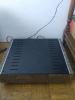
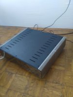
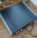
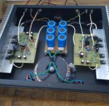
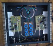
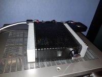
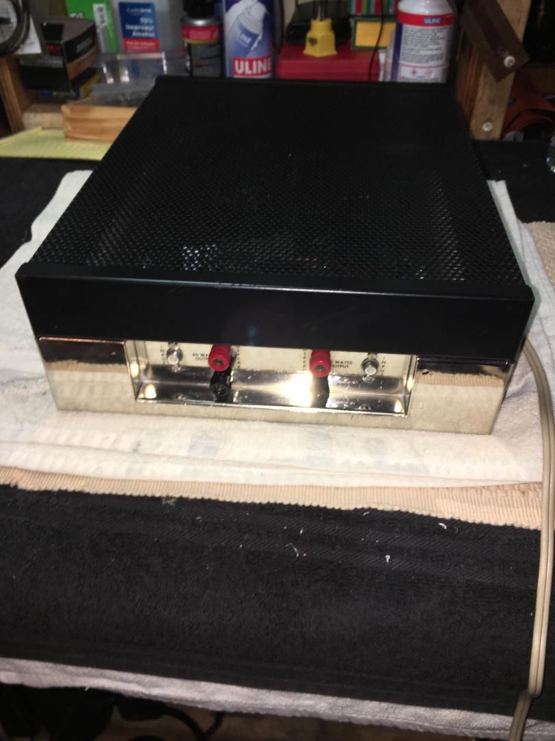
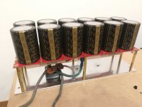
Amcron DC300A restoring. Got this for very low price, but it had some work to do:
Everything was pretty much dirty & corroded and one channel was distorting (lack of bias, faulty bias regulator transistor mpsa93). Knobs were missing.
Things I did:
Gave it a good cleaning work to get rid of corrosions.
Changed all 10V zener diodes (using 1.3W types), all small capacitors and those mpsa93 bias regulator transistors.
After that, OP amp voltage rised from lowish 9.85/9.80volts to +/- 10.01volts.
Bias settled in for steady 360mV for both channels. Adjusted in/out offset referring to service manual. 0mV +/- 1mV for both channels. Power supply filtering caps are still good to go, no need to change. Outputs are factory original RCA's too (they all have pencil markings on them so are likely matched).
Oh man this amp sounds so good! Who said these makes harsh sounding high end? Propably they had faulty DC300A or something other things horribly wrong. In good working order, DC300A produces very transparent, low distortion flawless sound and there is absolutely nothing annoying. Bass response is amazing thanks to DC-circuitry and high damping. Dead silent too, no hum no noise at all.
Finished Symasym AAK 1.4 DC offset 1.9mV and 3mV. Thanks for nice amp
No inside pics sorry
Inside pics and bias set to 140mA, no hum no noise trafo 500W
Attachments
Nice builds here!
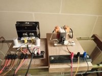
Here is something simple I put together last week.
The mini class D amps are popular, so I thought I would make a mini class A from a pair of Chinese JLH 69 kit-boards with mosfet outputs.
Powered from a 19V switched laptop charger and Iq around 0,7A/channel. Does not get too hot, and sounds ok too.
Attachments
Yes, I bought some when I started building class A amps, this is the first time I used it though. No heat in the box ")
I also have some metal sheet with square holes that was once grilles on some old speakers, and that looks even nicer, so I'm saving it for some other project.
I also have some metal sheet with square holes that was once grilles on some old speakers, and that looks even nicer, so I'm saving it for some other project.
Impressive looking chip amp. Good work.[/IMG][/IMG]
Hard to get an impression of size from the photo - but I think they must be bigger than what they appear at first glance. THat's a great collection. Be proud.
My Diy, made in Brazil, PC, Raspbery dac and P3a amplifier, diy board.
the speakers are diy. Sorry about my English
P101 ESP Mosfet
Hi All,
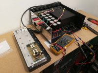
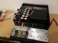
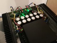
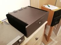
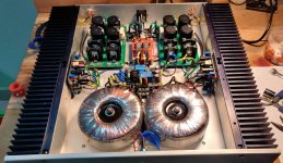
My P101c amp project that has been filling my winter evenings here in the UK and quite some time of pre planning.
Happy to say boards are easy to build, great info pack provided by Rod.
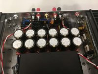
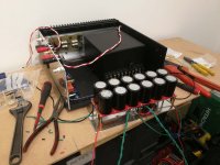
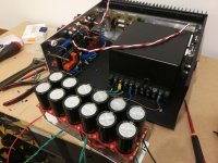
Case is recycled from an old Rowland Research Amp, transformer also.
Mains power control is a Holton AC controller, with his Audio Solid State Relay (HPA-SS/Relay One) soldered to speaker terms.
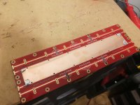
DC cap bank boards are Moutoulos ™ modified with circular saw, copper and soldering iron.
Low voltage testing with no load on my picoscope, no bias, showed no waveform distortion 10Hz to 30kHz. I didn't bother going any higher. Output was very flat across this frequency range.
DC offset at speaker terms is left 25mV and right -27mV
I built the high power version, as my transformer is 39-0-39v, so two sets of output devices. Bias is 3mV higher across Q8/Q9 than Q10/Q11, this is the same for both amp modules? With Rods starter bias I get next to no heat at heat sinks, so have gone to 75% of his max. Some heat at the sink now, but very little.
Sound so far is great, detailed but not bright. See how it breaks in / how I get used to it.
Zero noise at the speakers with no music playing. I tried to keep circuit away from each other as much as possible. Also kept the wiring to a minimum via design.
Hi All,
My P101c amp project that has been filling my winter evenings here in the UK and quite some time of pre planning.
Happy to say boards are easy to build, great info pack provided by Rod.
Case is recycled from an old Rowland Research Amp, transformer also.
Mains power control is a Holton AC controller, with his Audio Solid State Relay (HPA-SS/Relay One) soldered to speaker terms.
DC cap bank boards are Moutoulos ™ modified with circular saw, copper and soldering iron.
Low voltage testing with no load on my picoscope, no bias, showed no waveform distortion 10Hz to 30kHz. I didn't bother going any higher. Output was very flat across this frequency range.
DC offset at speaker terms is left 25mV and right -27mV
I built the high power version, as my transformer is 39-0-39v, so two sets of output devices. Bias is 3mV higher across Q8/Q9 than Q10/Q11, this is the same for both amp modules? With Rods starter bias I get next to no heat at heat sinks, so have gone to 75% of his max. Some heat at the sink now, but very little.
Sound so far is great, detailed but not bright. See how it breaks in / how I get used to it.
Zero noise at the speakers with no music playing. I tried to keep circuit away from each other as much as possible. Also kept the wiring to a minimum via design.
Attachments
-
 IMG_20200203_182257.jpg263.8 KB · Views: 492
 -
 IMG_20200203_223102.jpg277 KB · Views: 452
 -
 IMG_20200204_181618.jpg312.1 KB · Views: 512
 -
 IMG_20200204_181628.jpg311.8 KB · Views: 547
 -
 IMG_20200204_185223.jpg289.9 KB · Views: 565
 -
 IMG_20200204_195808.jpg296.3 KB · Views: 607
 -
 IMG_20200204_223449.jpg246.6 KB · Views: 1,521
 -
 IMG_20200206_204334.jpg238.3 KB · Views: 1,654
 -
 IMG_20200203_222453.jpg387.5 KB · Views: 588
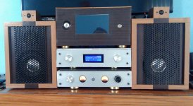
This is my latest amplifier project thanks to suggestions and help from this forum. Many thanks go to Mooly for suggesting me to use the LM3886 chip amplifier. I used two of this chip to build a stereo amplifier. I can only say, it sounds too good for a chip! The amplifier is very economically built and is supplied power from a linear split power supply using old technology. The output is fed to two Wharfedale 250W RMS Titan 12'' speakers on stands. The speakers are of the passive type. The input is fed from a Raspberry Pi 3B+ with an IQAudIO DAC Pro. The Pi player is operated from a terminal using Unix style commands.
Attachments
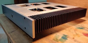
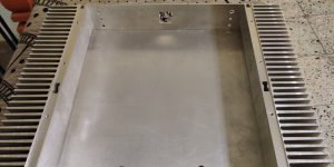
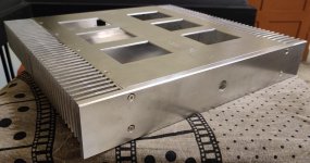
A new home for my PeeCeeBee v4. I had a couple of heatsinks lying around - leftovers from another project. Wanted something that looked sleek.
Used a (linux) freeware called Solvespace for the drawings. It's not fancy, but it does the job. and I dont know the big autocad programs anyway
Random orbital router to get the surface finish. Used 60, then 120 grit. Deep blue anodized heatsinks - they are defly overkill.
Still work in progress. Letterings being a problem. and I havent found something suitable for the top mesh. couldn't find steel mesh in the shops here (it's a small town in South India)
Attachments
Last edited:
- Home
- Amplifiers
- Solid State
- Post your Solid State pics here