My frist bi-amp.
plz don´t hit me, I know is looking ugle
An externally hosted image should be here but it was not working when we last tested it.
DxS rules!!!!
")
Totally, well done mate! Proper DIY, awesome
Thanks mate
Cngratulations on your fine amp!
Thanks bigun
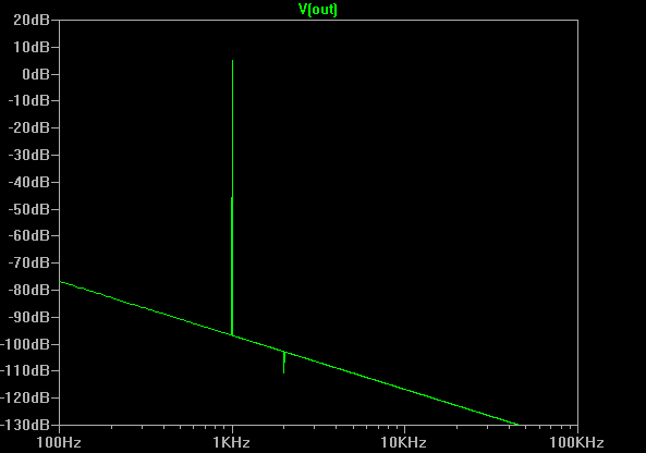
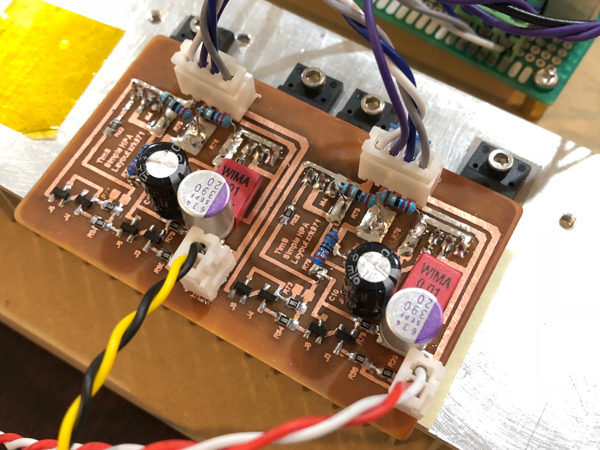
Hand-Etched Prototype of DC-coupled Simple High Performance SE Class A HPA designed by TimS. Sims show about 0.75PPM THD for 5vpp into 55ohms, and in a pinch can drive 1wrms into 8ohms with 0.0004%THD with 400mA bias. Qnty 4 x BF862's a BC860 BJT and two P-channel TO220 MOSFETs. Example below is using 2SJ313's. Fired up first time and stable DC offset of 5mV, bias is set at 116mA. Very powerful sound.
More info here:
Simple High Performing Headphone Amp
predicted FFT for 5vpp into 55ohms at 180mA bias:
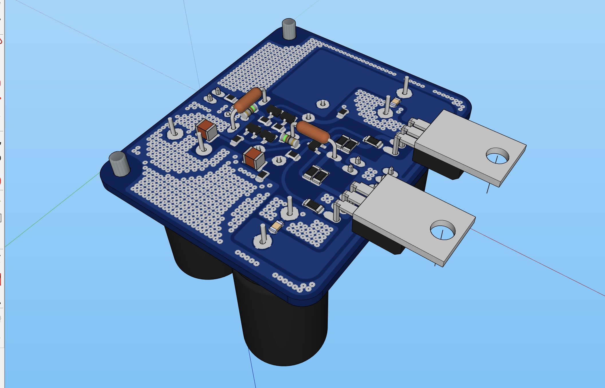
JPS64 has made pro-layout, will order boards soon:
More info here:
Simple High Performing Headphone Amp
predicted FFT for 5vpp into 55ohms at 180mA bias:
JPS64 has made pro-layout, will order boards soon:
Last edited:
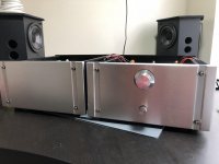
Dx Classic II in bi amp scheme
Hello folks,
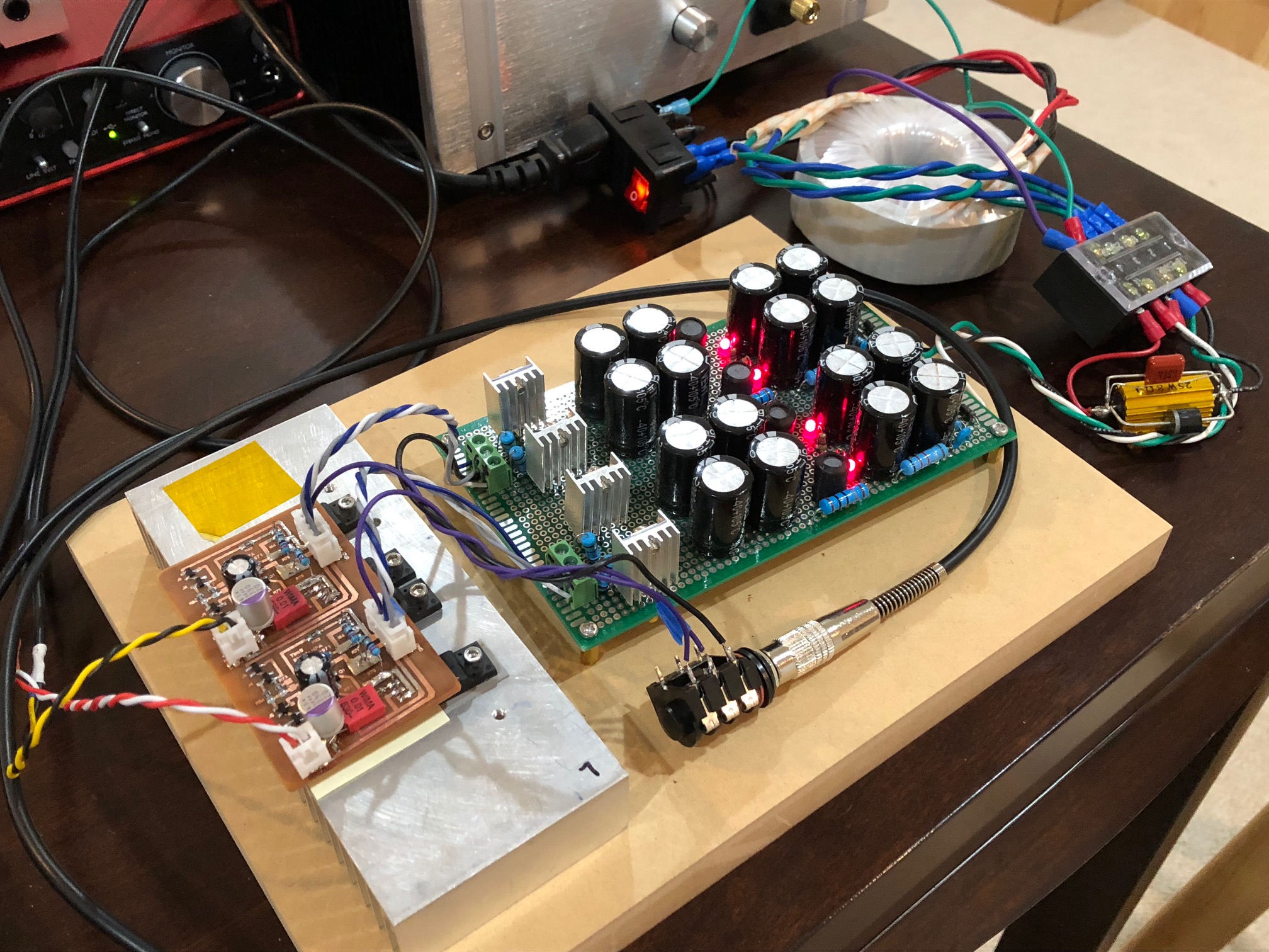
This is my first DIY amplifier project.
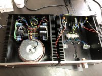
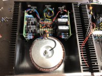
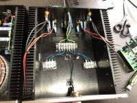
It has 2 cases, one for the toroid and power boards, and another for the amp boards.
Here goes some pics of them.
I'm using Dx Classic II amps, from Mr. Mergulhao.
They sound amazing! Believe me!
PS: the amps are not in place yet, 'cos I'm waiting for 2 more boards I've bought from Mr. Mergulhao.
Thx.
Hello folks,
This is my first DIY amplifier project.
It has 2 cases, one for the toroid and power boards, and another for the amp boards.
Here goes some pics of them.
I'm using Dx Classic II amps, from Mr. Mergulhao.
They sound amazing! Believe me!
PS: the amps are not in place yet, 'cos I'm waiting for 2 more boards I've bought from Mr. Mergulhao.
Thx.
Attachments
Holy Cow Christian!!Hello folks,
This is my first DIY amplifier project.
It has 2 cases, one for the toroid and power boards, and another for the amp boards.
Here goes some pics of them.
I'm using Dx Classic II amps, from Mr. Mergulhao.
They sound amazing! Believe me!
PS: the amps are not in place yet, 'cos I'm waiting for 2 more boards I've bought from Mr. Mergulhao.
Thx.
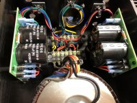
Ground, I guess.Hey Christian, nice looking amp! Just wondering what is black wire that goes on top of transformer...?
Ground, I guess.
You should not connect anything there
that's why I'm asking.Is because of the magnetic field?You should not connect anything there
"GHOST" LMOSFET
HAHA
Reading the above post!
Had created a shorted turn unknowingly yesterday. Initially I wanted the transformers mounted to a plate that I had made, however, they were too heavy and decided to tap the faceplate. When I tapped the faceplate, I kept the mounting bolt long enough to mount to both sides! DOH! She ran HOT!!
Anyway, here's a prototype dirty pic.. Raspberry PI underneath

You should not connect anything there
It is a grounding to the chassis...
OK, good to know
HAHA
Reading the above post!
Had created a shorted turn unknowingly yesterday. Initially I wanted the transformers mounted to a plate that I had made, however, they were too heavy and decided to tap the faceplate. When I tapped the faceplate, I kept the mounting bolt long enough to mount to both sides! DOH! She ran HOT!!
Anyway, here's a prototype dirty pic.. Raspberry PI underneath
View attachment 686405
Wow, superb build! Which circuit is it?
"Ground, I guess."
If it is, and the other end of the trafo bolt is connected to the chassis, then there will be a shorted turn.
That's why this forum is amazing!!!
Thank you so much for having warned me!!
For those who ended up here looking for "shorted turn" in trafos, see this thread: Toroids, mounting bolts, and shorted turns
Thanks again!
Wow, superb build! Which circuit is it?
Some little twists and enhancements on a Randy slone lmosfet design. The raspberry pi and dac are my own designs to control the amp power and use that PCB 5v supply. The dac I had to build so that I could run with no audio cables etc... I wanted no wires but had to for the transformers. Everything else is built onto the PCB. Soft Start and dc protection and relays etc... Lots of work but it's finally showing up. All in a mini 3u. Somewhere near 200w/ch. There's no caps in the signal chain either, a perk from end to end design. She just needs to be tidied up. Can run anything that I raspberry pi will run. Got Spotify on volumio at the moment. Just plug it in and speakers and let it work!
Some little twists and enhancements on a Randy slone lmosfet design. The raspberry pi and dac are my own designs to control the amp power and use that PCB 5v supply. The dac I had to build so that I could run with no audio cables etc... I wanted no wires but had to for the transformers. Everything else is built onto the PCB. Soft Start and dc protection and relays etc... Lots of work but it's finally showing up. All in a mini 3u. Somewhere near 200w/ch. There's no caps in the signal chain either, a perk from end to end design. She just needs to be tidied up. Can run anything that I raspberry pi will run. Got Spotify on volumio at the moment. Just plug it in and speakers and let it work!
Very nice. Very very nice. Did I mention that was VERY nice?
Some little twists and enhancements on a Randy slone lmosfet design. The raspberry pi and dac are my own designs to control the amp power and use that PCB 5v supply. The dac I had to build so that I could run with no audio cables etc... I wanted no wires but had to for the transformers. Everything else is built onto the PCB. Soft Start and dc protection and relays etc... Lots of work but it's finally showing up. All in a mini 3u. Somewhere near 200w/ch. There's no caps in the signal chain either, a perk from end to end design. She just needs to be tidied up. Can run anything that I raspberry pi will run. Got Spotify on volumio at the moment. Just plug it in and speakers and let it work!
Very nice indeed! Did you notice any problems with the raspberry pi's wi-fi/bluetooth range using the aluminum case? I have a similar project in mind and was worried that the chassis would make the signal poor (I was thinking about installing an external antenna, but if you have no problems, I will go the simple way).
Congratulations!
- Home
- Amplifiers
- Solid State
- Post your Solid State pics here