There's absolutely zero reason to be frightened of surface mount components. I find the bigger ones (1206) much easier to deal with than through-hole components.
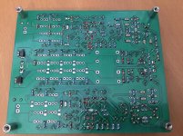
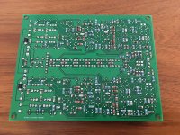
Here's a couple of photos of one of my latest amps part way through loading, to show details of the process. This is built with 0204 MELF resistors (similar dimensions to a 1206, but round), 1206 capacitors, MELF diodes, and SO-8 ICs.
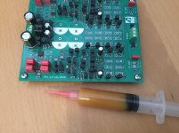
I don't use hot air - I simply use a reasonably fine soldering iron tip (these were done with a Metcal STTC-037 tip, which is a 1.8mm chisel. I use gobs and gobs of RMA flux (in the syringe) to coat every pad, then apply some solder to one pad for each component. You can see this on some of the components - I ran out of 1Ω resistors. Then I hold the component in place with tweezers, reflow the solder, then solder the other end.
The additional flux is really really important to ensure good quality joins. If you don't have ample flux on the work, the reflow for the first pad just doesn't work properly.
RMA flux is the only stuff I use - both personally and in the lab I run for work. The reason for this is that it works well to clean oxides, and - importantly - is really easy to get off the PCB afterwards. Many industrial processes spec no-clean flux, which you can leave on the PCB for consumer junk. No-clean flux doesn't work very well to remove oxides though, so you've then got to be really anal about component manufacturing dates and storage. On top of that, if you do want to clean the flux off, it's all-but impossible to remove.
Same applies to the flux in the solder wire - that's gotta be RMA too, for exactly the same reason. Luckily all the solder manufacturers (Kester, Multicore, etc) cater to PITA old EEs like me, so the stuff is easy to buy.
After I'm finished doing the surface mount parts, the board gets dipped in boiling water from the kettle to heat it up, then I splash a little Safewash (Electrolube Safewash Original 400ml from Electrolube Mektronics Australia) on and scrub it with a toothbrush. Safewash is a water soluble detergent-based flux remover, and works a treat on RMA flux, especially if everything is nice and hot.
Then I add the through-hole components. If everything is nice and new, as it is for this PCB, I generally don't worry about additional flux for the through hole stuff - what's in the solder is plenty. Once that's all done, the PCB gets a second scrub in hot Safewash, followed by a rinse in hot water and a bake in the oven for a couple of hours at 60-80 degrees.
There's just way too many advantages with surface mount parts - components on both sides, higher stuffing density, better quality components, lower parasitics - not to use them.
Edit: And I just spotted a couple of pads (caps - top right of the PCB lower) that I missed.
Here's a couple of photos of one of my latest amps part way through loading, to show details of the process. This is built with 0204 MELF resistors (similar dimensions to a 1206, but round), 1206 capacitors, MELF diodes, and SO-8 ICs.
I don't use hot air - I simply use a reasonably fine soldering iron tip (these were done with a Metcal STTC-037 tip, which is a 1.8mm chisel. I use gobs and gobs of RMA flux (in the syringe) to coat every pad, then apply some solder to one pad for each component. You can see this on some of the components - I ran out of 1Ω resistors. Then I hold the component in place with tweezers, reflow the solder, then solder the other end.
The additional flux is really really important to ensure good quality joins. If you don't have ample flux on the work, the reflow for the first pad just doesn't work properly.
RMA flux is the only stuff I use - both personally and in the lab I run for work. The reason for this is that it works well to clean oxides, and - importantly - is really easy to get off the PCB afterwards. Many industrial processes spec no-clean flux, which you can leave on the PCB for consumer junk. No-clean flux doesn't work very well to remove oxides though, so you've then got to be really anal about component manufacturing dates and storage. On top of that, if you do want to clean the flux off, it's all-but impossible to remove.
Same applies to the flux in the solder wire - that's gotta be RMA too, for exactly the same reason. Luckily all the solder manufacturers (Kester, Multicore, etc) cater to PITA old EEs like me, so the stuff is easy to buy.
After I'm finished doing the surface mount parts, the board gets dipped in boiling water from the kettle to heat it up, then I splash a little Safewash (Electrolube Safewash Original 400ml from Electrolube Mektronics Australia) on and scrub it with a toothbrush. Safewash is a water soluble detergent-based flux remover, and works a treat on RMA flux, especially if everything is nice and hot.
Then I add the through-hole components. If everything is nice and new, as it is for this PCB, I generally don't worry about additional flux for the through hole stuff - what's in the solder is plenty. Once that's all done, the PCB gets a second scrub in hot Safewash, followed by a rinse in hot water and a bake in the oven for a couple of hours at 60-80 degrees.
There's just way too many advantages with surface mount parts - components on both sides, higher stuffing density, better quality components, lower parasitics - not to use them.
Edit: And I just spotted a couple of pads (caps - top right of the PCB lower) that I missed.
Attachments
Last edited:
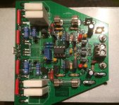
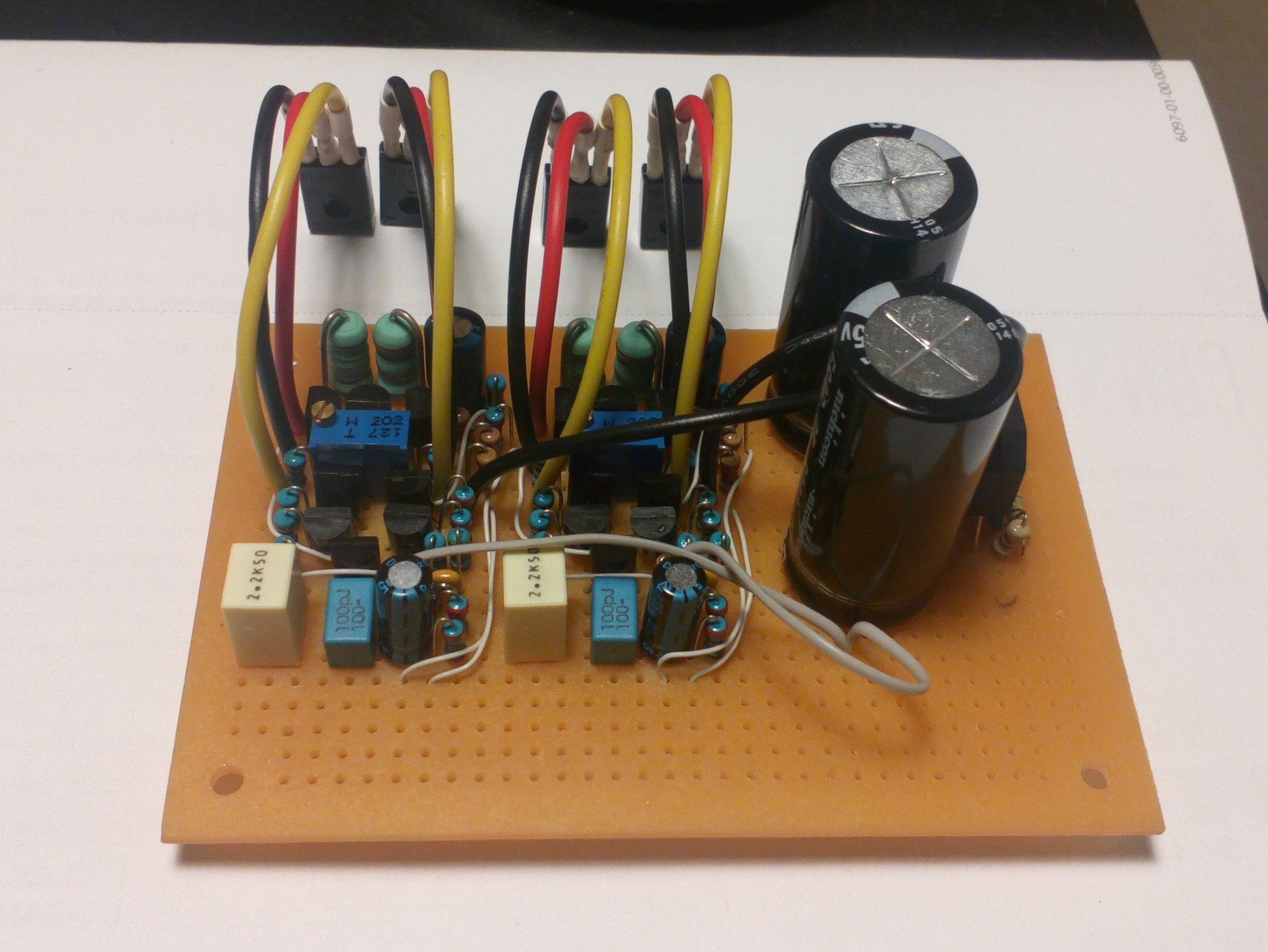
First version were built in 1988, this last is current feedback +50V/0/-50V or more, double sided with ground planes, non SMD elements, pure discrete construction, and total symmetrical scheme with servo null. Rail to rail voltage on driver, all DC coupled, compound type end stage, 100*84mm with direct mount on heat sink. Exist in SK/SJ, Exicon and IRFP output transistor version.
Attachments
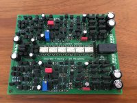
Here's a super-simple discrete preamp/headamp I've knocked together, using just 148 transistors! It includes relay-based 6-bit stepped attenuator and DC servo. The amplifier is based on the cascaded diamond topology.
This represents about ten hours solid sticking components on the board, plus a pretty stiff neck from sitting hunched over for so long.
This represents about ten hours solid sticking components on the board, plus a pretty stiff neck from sitting hunched over for so long.
Attachments
Suzy!
Okay, it's a thing of beauty for sure. Even designing the PCB was an undertaking, and you did a good job it would seem.
Now for the question. Does it work? Knowing how these circuits do work and sound, I imagine that as long as there are no problems, it must sound great (in that it has no sound of it's own).
I am impressed.
-Chris
Does it work? Knowing how these circuits do work and sound, I imagine that as long as there are no problems, it must sound great (in that it has no sound of it's own).
Work is such a big word.
At the moment, on balance, taking everything into account, and recognising that it's supposed to be an amplifier, and not a 9.2MHz oscillator, I'm going to have to say no, it, umm, doesn't work.
Early days yet though - I've taken a whole lot of steps from the standard cascaded diamond that I've tamed to here all at once.
That said, it's kept it's smoke in, the relay attenuator section appears to be working nicely, the regulator works, all the bias points I've probed thus far appear to be sensible, it's pulling 250mA from +/-15V supplies, which appears to be about on the money.
And it's putting out a healthy +14dBm tone at 9.2 MHz, which probably isn't quite optimal...
I'll figure out which stage is the one singing by seeing if I can attenuate the tone and go from there. I'm confident that I've got enough compensation knobs that I can twiddle that I'll be able to tame it without a board respin. Early days yet!
I am impressed.
Thanks Chris!
It’s not complex really - there are two channels plus a regulator. Each side has just 69 transistors, plus 10 for the regulator. The amps can be further broken down to 23 transistors for the input amp, 39 for the output stage, and 7 for the DC servo. I’ve just done functions that you’d usually use a packaged opamp discretely, is all.
The benefit is complete control - I can optimise distortion performance, speed, power consumption, noise, really whatever I like by just changing some resistor values.
Chris - I’ve sorted the oscillation - I was just being a bit over enthusiastic with my output stage compensation and sailing a bit close to the wind running with an output stage gain of 4. I increased the output stage gain to 11 and it quietened it down. I’ve since redone the compensation more conservatively and it’s stable now with gains of 4 in both input and output stages.
Nice simple amplifier! See you on hackaday
")
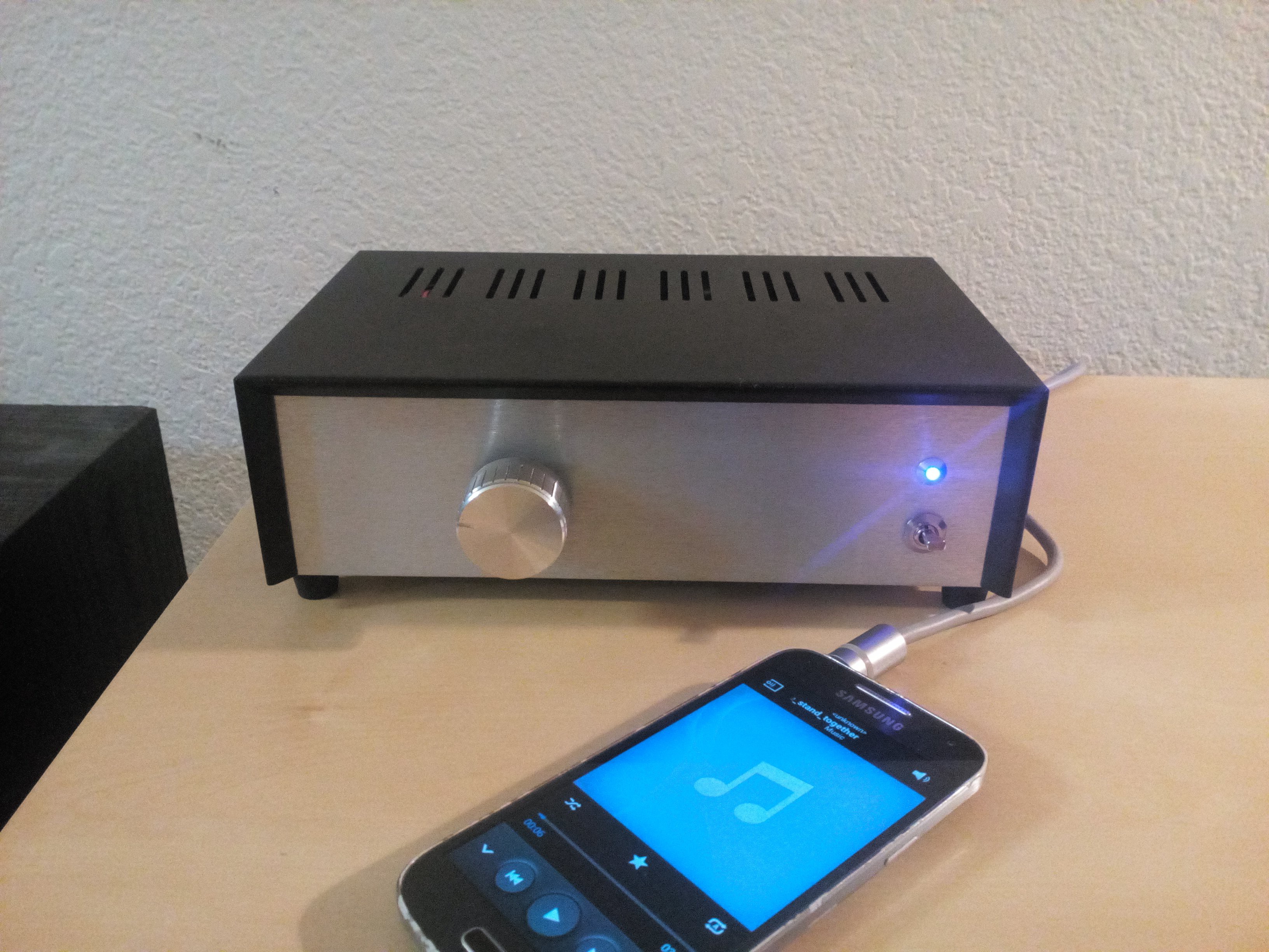
From Alpha - topic, temporary Alpha20 build to old, already ditched framework. I think it looks nice on it's own kinda way, even stripped down. But I'll soon tear it apart once more and get the frame done right.
Hello Juntuin,
very nice build. its pity you plan to tear it down...
regards
Prasi
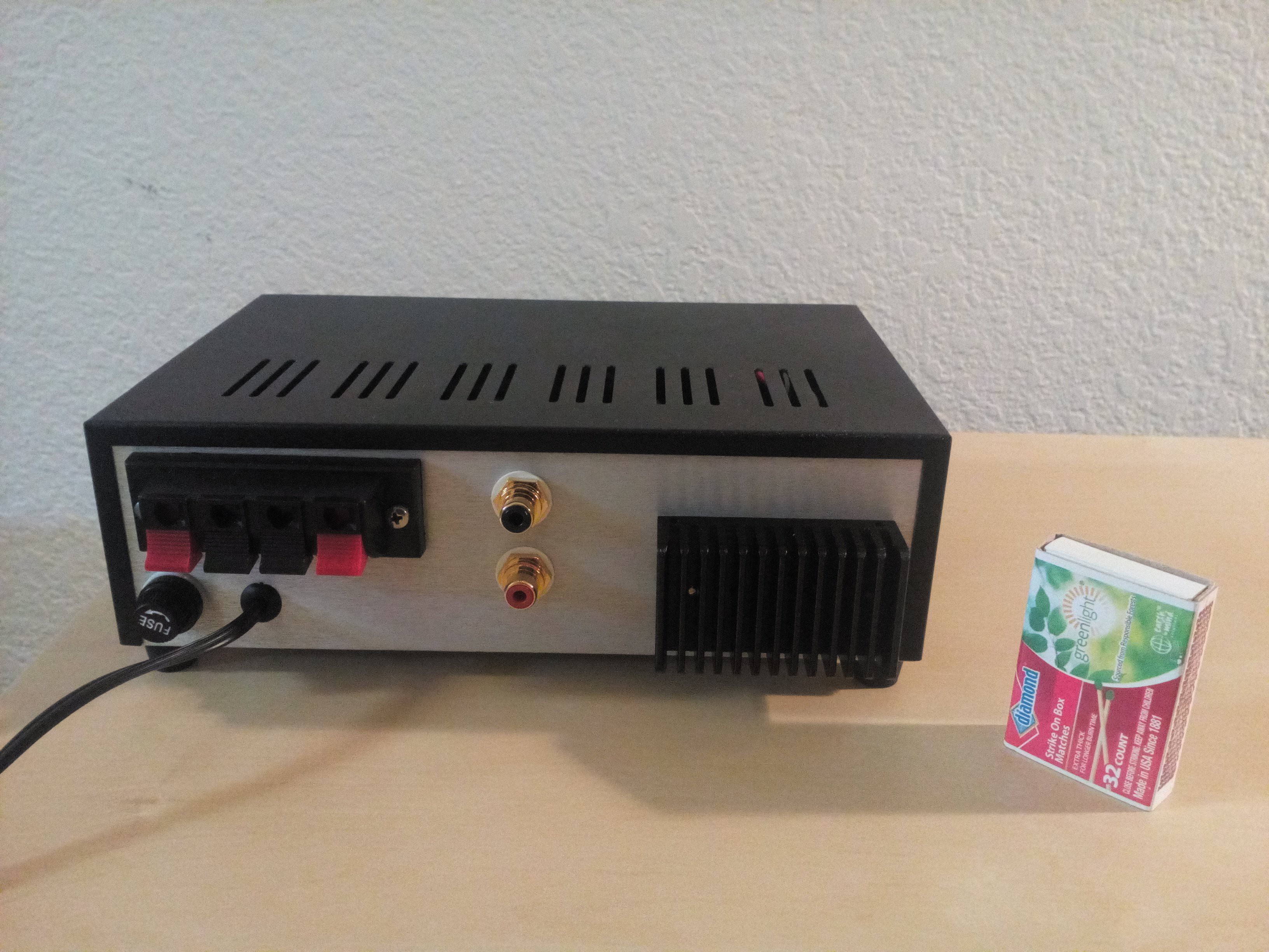
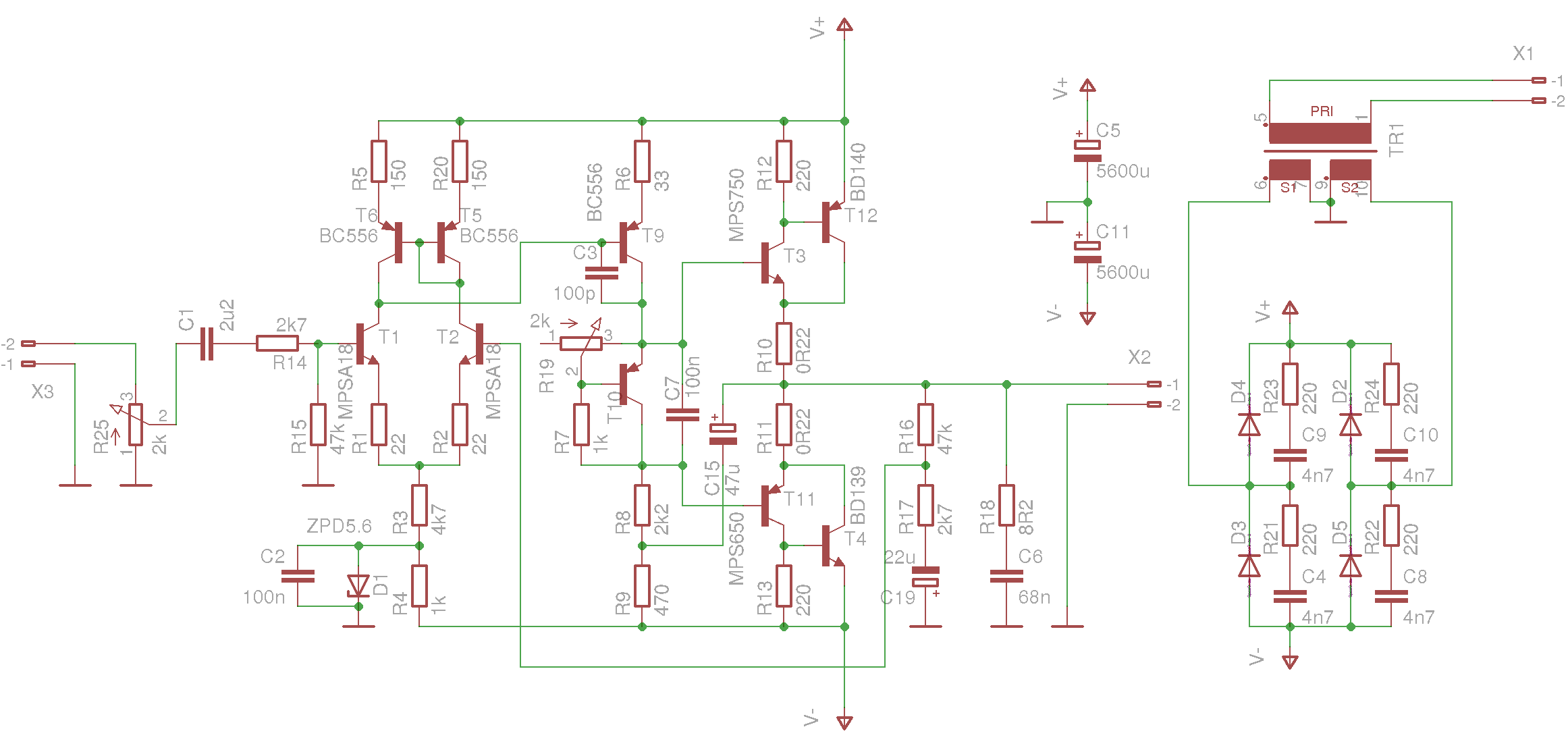
2 x 7W audio amplifier with BD139 & BD140
hello,
nice build, very compact!. any reason why you used those zobel values 8r2 and 68n? Also whats the value of T10?
regards
Prasi
Last edited:
Hello Juntuin,
very nice build. its pity you plan to tear it down...
regards
Prasi
Hi Prasi!
I only tear it down for frame paint, couple of holes, few plates etc
so it will remain quite the same but cleaner.I don't have any good explanation. I'm using short speaker cables so inductive load is not an issue in my case. Snubbers with 100n caps are prepared for the worst.any reason why you used those zobel values 8r2 and 68n?
Any type of silicon bipolar transistor will do, even PNP ones.Also whats the value of T10?
- Home
- Amplifiers
- Solid State
- Post your Solid State pics here