Finger trouble, here’s another try:
Ok, nothing ventured nothing gained..
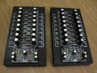
here is the latest version of my inductance loaded Class A amplifier:

If you look closely you’ll see the transformer primary is taped up, that’s because I’m using it as an inductor, only the secondaries are used. It’s one of a pair BTW.
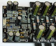
Here’s a board nearing completion:

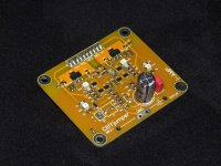
I can’t remember why I took this one:

The heat sinks are ‘live’ - to avoid isolating pads - so they are secured to the inductor using plastic screws and stand-off’s.
Oh, I should say, from a 6V supply (I use SLAs), it produces 6W into 8 Ohms at 0.003% THD - according to LTSpice. I’m toying with the idea of reducing that to about 4W - not sure.
Ok, nothing ventured nothing gained..
here is the latest version of my inductance loaded Class A amplifier:
If you look closely you’ll see the transformer primary is taped up, that’s because I’m using it as an inductor, only the secondaries are used. It’s one of a pair BTW.
Here’s a board nearing completion:
I can’t remember why I took this one:
The heat sinks are ‘live’ - to avoid isolating pads - so they are secured to the inductor using plastic screws and stand-off’s.
Oh, I should say, from a 6V supply (I use SLAs), it produces 6W into 8 Ohms at 0.003% THD - according to LTSpice. I’m toying with the idea of reducing that to about 4W - not sure.
")
operator16
How did You find those flat SMD resistors ?
I have made a few prototypes with them and they seem to be not as linear as the metalised minimelf or tht resistors. In all cases when those flat resistors were used with higher amplitudes the results were worse than metalised ones.
What brand are yours?
Regards
Peter
All parts work well because a 4-layer board with double copper thickness is used. No problem.
cmd resistors lie on a solid ground polygon, so the distributed capacitance effect works, image plane effect. There are no ground tracks and power supply, only signal tracks on the board.
cmd resistors lie on a solid ground polygon, so the distributed capacitance effect works, image plane effect. There are no ground tracks and power supply, only signal tracks on the board.
Attachments
Last edited:
805 size are usually 100mW or 125mW.operator16
How did You find those flat SMD resistors ?
I have made a few prototypes with them and they seem to be not as linear as the metalised minimelf or tht resistors. In all cases when those flat resistors were used with higher amplitudes the results were worse than metalised ones.
What brand are yours?
Regards
Peter
This compares to the 600mW I normally use for leaded metal film resistors.
They come in metal oxide and metal film.
Use the metal film (much more expensive) and place sufficient in series to resist the applied voltage you have.
AndrewT
Thanks a lot.
I was using vishay minimelf resistors and they are fantastic, but it is hard to get them in some values.
I must do a bit of the research for the good flat ones.
diyralf
I have build a few full SMD prototypes with standard flat 1206 resistors and every time they wer way worse than good old THT ones.
Regards
Regards
Were you using metal film 25ppm/C 250mW smd in 1206 package?..........SMD prototypes with standard flat 1206 resistors and every time they wer way worse than good old THT ones.
........
These probably compare well to metal film 50ppm/C 600mW through hole leaded.
AndrewT
I was using :
https://www.tme.eu/en/Document/13f9d0766a2524c5bd28b9996aed3ce0/general.pdf
Thick film resistors, whatever it means. I could not find any information if this was a metal film or some other kind of restive material used.
Regards
I was using :
https://www.tme.eu/en/Document/13f9d0766a2524c5bd28b9996aed3ce0/general.pdf
Thick film resistors, whatever it means. I could not find any information if this was a metal film or some other kind of restive material used.
Regards
Thick film is metal oxide. That explains why you are finding poor performance. The low power handling and the high tempco are combining to make the resistor values vary with current passing.AndrewT
I was using :
https://www.tme.eu/en/Document/13f9d0766a2524c5bd28b9996aed3ce0/general.pdf
Thick film resistors, whatever it means. I could not find any information if this was a metal film or some other kind of restive material used.
Regards
You should be using thin film (=metal film) to match the performance of metal film leaded resistors.
Many hold stock of very expensive 0.1% 15 to 25ppm/C thin film resistors.
Some retailers are now starting to stock 1% 25ppm/C thin film in smaller quantities that have become affordable.
For thos interested, here is a direct comparison Thin Film vs. Thick Film resistors.
Thin and thick film >> Resistor Guide
Thin and thick film >> Resistor Guide
I had a lot of problems with thick film chip resistors recently. See Suzy's Blog: Measuring a MOSFET Power Amplifier.
This plot says it all - distortion performance is absolutely trashed using thick film resistors in the feedback network.
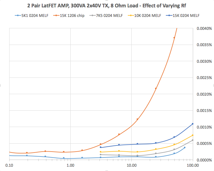
I'm considering trying some thin film chip resistors as the MELFs are getting to be a PITA to find.
Yageo RT Series 25 PPM / C 1206 Thin Film Resistors - SMD | Mouser Australia
This plot says it all - distortion performance is absolutely trashed using thick film resistors in the feedback network.
I'm considering trying some thin film chip resistors as the MELFs are getting to be a PITA to find.
Yageo RT Series 25 PPM / C 1206 Thin Film Resistors - SMD | Mouser Australia
AndrewT
kct
suzyj
anatech
Thanks a lot!! Now it is more clear for me.
The only good SMD resistors I found are vishay melf/minimelf (quite expensive too), I have never had any problems with them, the results were always 100% from technical and sonic point of view.
BIG Thanks
Peter
kct
suzyj
anatech
Thanks a lot!! Now it is more clear for me.
The only good SMD resistors I found are vishay melf/minimelf (quite expensive too), I have never had any problems with them, the results were always 100% from technical and sonic point of view.
BIG Thanks
Peter
Attachments
I had a lot of problems with thick film chip resistors recently. See Suzy's Blog: Measuring a MOSFET Power Amplifier.
This plot says it all - distortion performance is absolutely trashed using thick film resistors in the feedback network.
I'm considering trying some thin film chip resistors as the MELFs are getting to be a PITA to find.
Yageo RT Series 25 PPM / C 1206 Thin Film Resistors - SMD | Mouser Australia
Lessons learned: Audio engineering with THT metal film resistors only.
Last edited:
Hi Peter,
When I was a younger tech, carbon composition resistors cost me $0.20 each! 5% values were "high accuracy" and I had only ever seen a 2% resistor, didn't even know there was a 1% resistor you could get.
Today, a Dale metal film resistor, 1/2 watt, can cost $0.93 each and higher. With that backdrop, I can't complain too much about today's prices. They can also sell for a much lower amount, but my point is, is that these parts can range in price but your situation is far better than it was easier in time.
-Chris
- Home
- Amplifiers
- Solid State
- Post your Solid State pics here