Thanks for sharing your veros guys! Each of them is product of hard work, kudos to all of you!
I would like to specially congratulate Bimo and PreSapian! Seriously guys, mind blowing job getting that much of integration with veros and also keeping the asthetix at high priority!

....... .......
I would like to specially congratulate Bimo and PreSapian! Seriously guys, mind blowing job getting that much of integration with veros and also keeping the asthetix at high priority!
.......
.......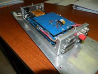
Thanks. It was just a matter of need. The panel it is mounted on was in between two technics SL 5100's, it's width defined by how close I could comfortably spin using the two tables without catching a shirt sleeve on the other tonearm and dragging the needle across the record. (btw, that sounds like lightning hitting the building) Depth was defined by the side edge height of the 5100's. Hence the need to stack the boards.
The D connectors were umbilicals to all the front panel controls for the mixer. It was a 19 inch 1RU panel with all the pots and switches. I can't find that panel anymore, I retired this puppy about 2 decades ago, and I believe I used the knobs for an 8 channel mike mixer. Hmm, I still have that, and it too is perfboard.. I'll have to find it and take pics as well for this thread..
edit: forgot to mention, all the copper shielding is actually solder wick. I cleaned the flux out of the wick, expanded it and put it over the wires. It allowed me some semblance of color coding for the wires in that spaghetti bowl..
jn
Depth was defined by the side edge height of the 5100's. Hence the need to stack the boards.The D connectors were umbilicals to all the front panel controls for the mixer. It was a 19 inch 1RU panel with all the pots and switches. I can't find that panel anymore, I retired this puppy about 2 decades ago, and I believe I used the knobs for an 8 channel mike mixer. Hmm, I still have that, and it too is perfboard.. I'll have to find it and take pics as well for this thread..
edit: forgot to mention, all the copper shielding is actually solder wick. I cleaned the flux out of the wick, expanded it and put it over the wires. It allowed me some semblance of color coding for the wires in that spaghetti bowl..
jn
Last edited:
..I still have that, and it too is perfboard... I'll have to find it and take pics as well for this thread...
Don't forget.
Thanks for sharing.
didn't.Don't forget.
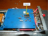
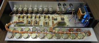
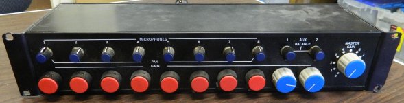
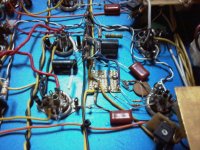
Here's the 8 input mike mixer. It also has two aux line in's as well, and all channels have panning.
I've no idea why I epoxied the resistors to within an inch of their lives.
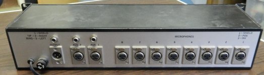
I wired the front panel to two 25 pin D connectors, as it was too busy to easily wire with this density.
Again I used the solderwick as a shield. What I really like is the ability to make my own color coded shielded cables. Note the input connectors are wired using home made shielded pair in color codes..brown/black, red/black, etc. In a complex chassis, this helped me tremendously. For the front panel, it allowed visual indication of correct wiring to all the pots.
jn
Attachments
Last edited:

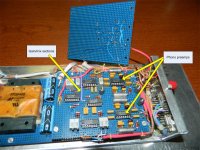
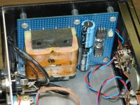
Link got lost, sorry.Little Vero Board for Murata DC-DC converter testing.

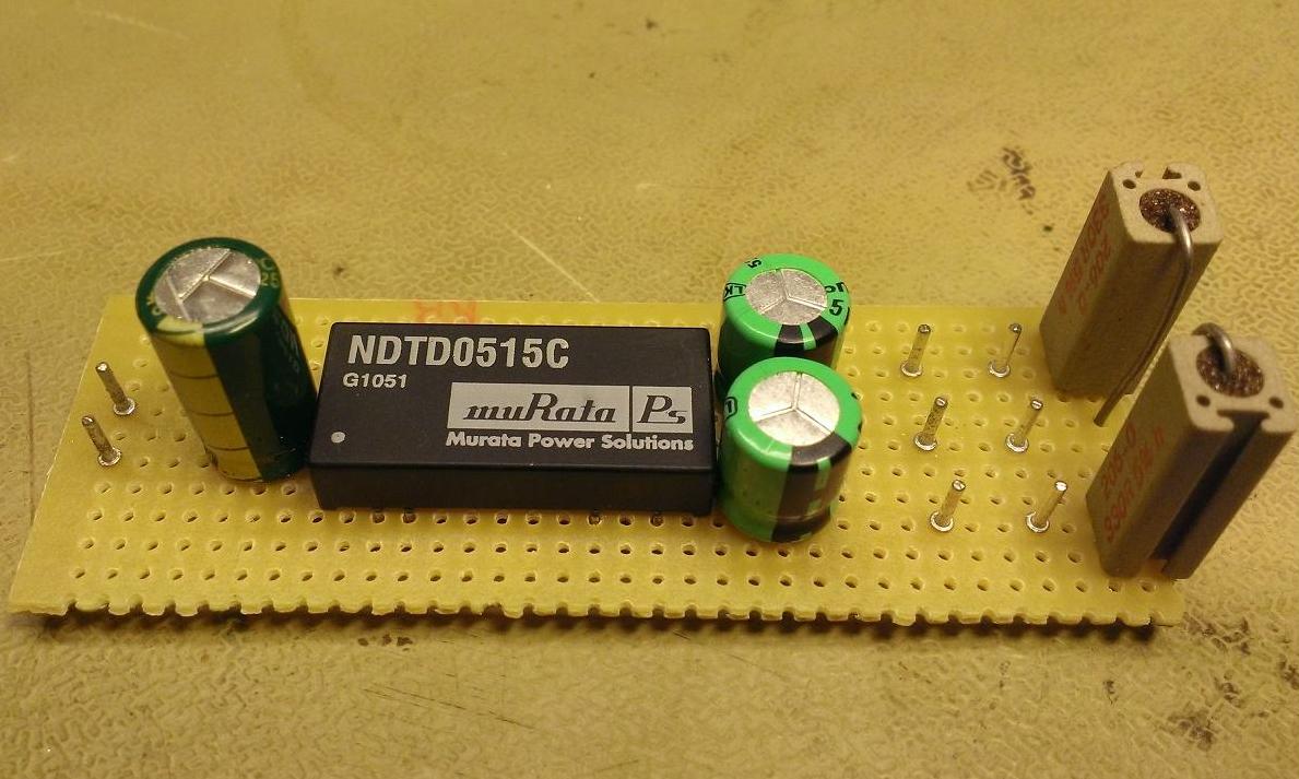
Hi!, this is a small square of vero board used as connection bridge, to avoid make extra holes on the chassis top plate. It's bonded to the chassis with a high temperature glue compound.
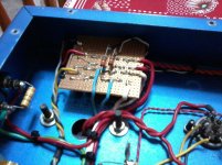
At the low right you can see a vertically mounted board that is the input valve cathode bias assy and GNFB intake.
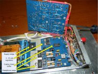
The second photo is a relay board that toggles between the 8 and 4 Ohm OPT terminals, and also shut off the speakers when a headphone jack is connected
At the low right you can see a vertically mounted board that is the input valve cathode bias assy and GNFB intake.
The second photo is a relay board that toggles between the 8 and 4 Ohm OPT terminals, and also shut off the speakers when a headphone jack is connected
Attachments
Very 'clean' Anders.
Thanks John.
It's a quick build in order to test this DC-DC converter out of it's normal environment.
Sorry for being OT, but will you share the results of your test here ?
Interesting part ...
I've had some issues with common mode switch noise traveling right through the internal transformer. Really high frequency so the small pri-sec capacitance coupled the switching noise. This little Vero board setup showed the same problem as I reported here
A solution could be a common mode choke but the DC-DC converter would still act as a transmitter. I've tried some different decoupling solutions but no success.
Maybe a separate thread dealing with this DC-DC converter?
Last edited:
- Home
- General Interest
- Everything Else
- Post Pictures of Your Vero Board Designs Here.