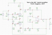
just a sketch...
Here is a sketch of a possible implementation.
Big fat WARNING: this is by no means a complete design. Although some quick simulations show that the attached schematic MAY work fine as it is, in practice it may not work at all for a number of possible reasons. You've been warned.
Here is a sketch of a possible implementation.
Big fat WARNING: this is by no means a complete design. Although some quick simulations show that the attached schematic MAY work fine as it is, in practice it may not work at all for a number of possible reasons. You've been warned.
Attachments
Hello!À how to you such variat?http://www.euronet.nl/~mgw/diy/amps/uk_tubeclone_2.html
Bastion said:Hello!À how to you such variat?http://www.euronet.nl/~mgw/diy/amps/uk_tubeclone_2.html
that's just a gainclone with a tube CF buffer in front of it. It has absolutely NOTHING to do with a "my_ref" style design such as those we are talking about here. They are completely different things. Please check the "my_ref" related threads by Mauro Penasa to understand why.
Hi Paolo,
your schematic is very interesting - I did not think of that simple when you said simple. It is a really smart solution - if it works. My only thoughts are that the stability of the lm3886 should be increased. Just a feeling right now but I think C2 and R9 as the only parts to garantee the stability are not sufficient in the practice. What about adding a small cap (anything about 100pF - 330pF) inseries with a small resistor in parallel to R3?
In addition we would need a good decoupling for the lm3886.
Best Regards
Flo
Floric said:your schematic is very interesting - I did not think of that simple when you said simple. It is a really smart solution - if it works.
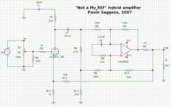
thanks for your kind words... would you believe meanwhile I have thought about an even simpler one?!
 (and cheaper too, just one triode and one coupling cap).
 Just connect a resistor between both current pump inputs as in Mauro's "Stasis" circuit. Connect the non inverting side to a simple grounded catode triode stage and the other side to ground through a properly sized resistor. Close the overall NFB loop to the catode of the input triode. That's all!
I have not yet tried to simulate this one to see if there may be some hidden problems... should do it ASAP.
BTW, it would be not only simpler and cheaper, but more fun too!
In fact, by simply changing a few connections you can change it from a "my_ref-like" to a "Stasis" design (you only have to open the overall NFB loop, move the triode output to the inverting side and connect the other c. pump input to the load).
Oh, and of course you can also just open up the loop to try out plain current drive mode. But of course this is true for just about any of these designs using c.p. for the output (well, that's likely of little use unless you have very well self-dumped crossoverless single driver speaker... or you're designing your own multiamped active crossover multi-way one).
Only drawback I can see of this simpler approach is ~ halving the loop gain. That's not a problem if you're following my philosophy (relatively high Z at the nominal load, decreasing on resonances for required speaker dumping and increasing as the load increase to avoid overcurrent clipping), but it would if you're trying to match the original "my_ref" specs instead. That being your goal, you can always use all the gain you need at the expense of input sensitivity; just add another voltage gain stage front end before the amplifier (out of the loop, at least I would put it there) to recover the required overall sensitivity and you're done.
My only thoughts are that the stability of the lm3886 should be increased. Just a feeling right now but I think C2 and R9 as the only parts to garantee the stability are not sufficient in the practice. What about adding a small cap (anything about 100pF - 330pF) inseries with a small resistor in parallel to R3?
simulations say there is some (tough not so big) phase margin. If I remember correctly, phase reverse at about 10MHz, while gain falls below zero around 1-2 MHz. Thus in principle it should be ok. Though I have only seen the results for an 8 ohm resistive load... haven't checked for different/reactive loads. But of course the only way to really know is to try it out in practice, simulations can't say everything anyway. If stability problems appears, something must be done about that... but if it ain't broken, don't fix it!
In addition we would need a good decoupling for the lm3886.
of course. I guess just copying the my_ref power supply & decoupling is likely the easiest way to get there.
thanks for your kind words... would you believe meanwhile I have thought about an even simpler one?! (and cheaper too, just one triode and one coupling cap).
Just connect a resistor between both current pump inputs as in Mauro's "Stasis" circuit. Connect the non inverting side to a simple grounded catode triode stage and the other side to ground through a properly sized resistor. Close the overall NFB loop to the catode of the input triode. That's all!
Oh, now you begin to make me kind of nervous. Which triode? Supply voltage? Is it possible to get a sketch of your idea?
Just connect a resistor between both current pump inputs as in Mauro's "Stasis" circuit. Connect the non inverting side to a simple grounded catode triode stage and the other side to ground through a properly sized resistor. Close the overall NFB loop to the catode of the input triode. That's all!
Beginning to think of a switch, some relays...
Oh, and of course you can also just open up the loop to try out plain current drive mode. But of course this is true for just about any of these designs using c.p. for the output (well, that's likely of little use unless you have very well self-dumped crossoverless single driver speaker... or you're designing your own multiamped active crossover multi-way one).
That's what I have here right now, fired by two my_rev, excellent.
Only drawback I can see of this simpler approach is ~ halving the loop gain. That's not a problem if you're following my philosophy (relatively high Z at the nominal load, decreasing on resonances for required speaker dumping and increasing as the load increase to avoid overcurrent clipping), but it would if you're trying to match the original "my_ref" specs instead. That being your goal, you can always use all the gain you need at the expense of input sensitivity; just add another voltage gain stage front end before the amplifier (out of the loop, at least I would put it there) to recover the required overall sensitivity and you're done.
In the moment I have only a little idea of the acoustical consequences (with my speakers). But I am thinking more and more of giving it a try. The circuit is quite simple, the ps is not that complicated too, just a piece of breadboard.
Thank you for your ideas!
Best regards
Flo
Originally posted by Floric
Oh, now you begin to make me kind of nervous. Which triode? Supply voltage? Is it possible to get a sketch of your idea?
here it is...
Attachments
Hi Paolo,
...was not that serious.
Very impressing schematics. It is getting simpler and simpler that one. If we wait for another two weeks, will the schematic then be free of resistors or free of caps (I am sure that you won't omit the tube and the LM3886)?
Just a couple of questions:
Are you going to build one? Which one?
Why did you choose R2, R3 and R9,R10 that big? I think 1k or 10k would be sufficient (some others would be reduced then too). Wrong?
The rating of R7 should be anything above 3W I think, if I read it right as 0.33, right?
But what's the rating of R1 and R13? All the others are uncritical.
BTW: I am talking about your version qith one tube, not the Stasis.
Best regards and thank you very much
Flo
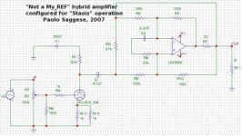
...and this is the same hardware reconfigured to implement Mauro's "Stasis" configuration instead. Very easy to switch from one to the other... though I would not do it with switches or relays.
...was not that serious.
Very impressing schematics. It is getting simpler and simpler that one. If we wait for another two weeks, will the schematic then be free of resistors or free of caps (I am sure that you won't omit the tube and the LM3886)?
Just a couple of questions:
Are you going to build one? Which one?
Why did you choose R2, R3 and R9,R10 that big? I think 1k or 10k would be sufficient (some others would be reduced then too). Wrong?
The rating of R7 should be anything above 3W I think, if I read it right as 0.33, right?
But what's the rating of R1 and R13? All the others are uncritical.
BTW: I am talking about your version qith one tube, not the Stasis.
Best regards and thank you very much
Flo
Originally posted by Floric Very impressing schematics. It is getting simpler and simpler that one. If we wait for another two weeks, will the schematic then be free of resistors or free of caps (I am sure that you won't omit the tube and the LM3886)?
well, I actually thought about omitting the cap. But, apart from requiring a dual HV supply for the tube, that would create a lot of problems about how to make sure that the 3886 inputs are always kept at ~ ground potential under any circumstance (e.g. when the tube is not conducting, with tube aging, etc). It would have surely required at least a servo, yet it would have been not so safe anyway if used with DC-coupled pre or sources...
Thus I feel the cap is safer and keeps everything simpler. And, given that it can be a good film or paper in oil one, plus that it's deeply polarized by some 150Vdc, it should not have too big an impact on the sound either.
Are you going to build one? Which one?
I guess I would try this last one... in fact I will likely do, as time permits. I am also curious to hear the difference with the "Stasis" version (there should be some really HUGE differences, for the output characteristics of the two are so radically different).
BTW, I am also thinking about a fully SS version using some FETs... trying to devise a SS design that sounds as good as a good tube amp is a challenge that intrigues me a lot...
But that will take some time, as I have so little to play with this things. Why did you choose R2, R3 and R9,R10 that big? I think 1k or 10k would be sufficient (some others would be reduced then too). Wrong?
that's a compromise... to keep things working as expected, they have to be quite larger than R1, R5 and R14 which, in turn, have to bee large enough to provide a proper load to the tube.
Increasing tube current (and reducing voltage accordingly to avoid excessive plate dissipation) it should be possible to use 10K for R1, making it possible to halve all the other too. But notice that R5,R14 and R7 values are closely related to establish the output characteristics of the amp, so their values cannot be changed "by chance" but require rethinking and re-verifying everything.
The rating of R7 should be anything above 3W I think, if I read it right as 0.33, right?
correct.
But what's the rating of R1 and R13?
with the suggested values tube current will be around 7mA, thus 2W is a safe choice for R1. R13 can be 1/4W or 1/2W.
Best regards and thank you very much
you're welcome.
If you're gonna try this out (and knowing my little spare time that's likely gonna happen before I'll be able to do it myself...
) please let me know your results!P.S.: as for the PSU, you can use the original "my_ref" or perhaps just about any "gainclone" scheme for the 3886 (I recommend using MUR860 diodes for rectification and Panasonic FC for filter caps), while for tube HV you may also use a 1:1 isolation transformer (with bridge rectifier if you have 230Vac mains or with a voltage doubler if you have 110 or 120 Vac) with a CRC or CLC filter.
P.P.S.: I'm leaving for a while... will be back to forum in July.
Andypairo said:Nice work Paolo, keep it up!
thanks... I'll keep you informed.
Which simulator (and model) are you using?
I recall that Mauro had to work on the spice model of the LM3886 to make it match the reality....
I'm using MicroCAP (the free "demo" version).
As for the LM3886 model, I use the generic op-amp model provided by MicroCAP filled with data-sheet values.
I'm not sure 'bout how close it is to reality (I haven't done any thorough simulated vs. measured results check).
As stated, these design ideas (calling them projects would be an overstatement to say the least) needs to be tested in practice and possibly/likely will need some refinement on the test bench.
Nevertheless, the model have proved to be good enough for getting a reasonable idea about how it will work in practice.
- Status
- This old topic is closed. If you want to reopen this topic, contact a moderator using the "Report Post" button.
- Home
- Amplifiers
- Chip Amps
- Possibility query: MyRef + Tube?