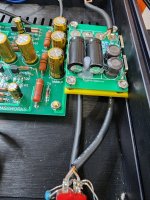
Here's a bipolar PCB layout. Boards are still on their way to me, so I have not verified the layout with actual parts yet. Caps are Panasonic EEU-FR1H471B
EEU-FR1H471B Panasonic | Mouser
There is room to lay them down to save 7.5mm in height if desired.
Boards are 57mm X 86mm. You can get a 5 pc. order for under $9 delivered, if you are willing to wait 2 - 3 weeks for standard freight. Double that price if you want them in just a few days.
I put together this today:
Thanks to @Mark Johnson and you for your service to the community!
I am going to use it with a Connex SMPS300REh +/-30V SMPS.
It’ll be the first time I use a SMPS for audio.

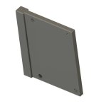
This is a zip file test to see if I can upload a 3D print file (*.3mf) for mounting the SMPS filter into a Modushop chassis. This is only a test (however, if it works, then great). Free for anyone to use and share. The picture shows the SMPS mounted in a Korg B1 chassis from the store. It simply slides down the middle slot and is held in place friction tight.
Attachments
Last edited:
https://www.mpja.com/02-29-24.asp?r=455562&s=15
I have never seen this splitter, very well done.
I have never seen this splitter, very well done.
"The only solution is to collect money as a group and pay one of the constructors on this forum to construct a filter for eg 7A and 50V. It's not worth crying and whining!!!"
Gee, thanks, Asimze!
BTW,
who's "crying & whining" again?
I feel like I'm in Middle School again, with such treatment.
NOT ON MY DIYAUDIO

(Almost sorry I asked- NOT!)
p.s., I believe putting two filters in parallel might work- any knowledgeable members with expertise to explain why it can/cannot work?
Thank you.
Thank you for the helpful
(and civil)
answer.
It looks as though running to boards in parallel can be done, provided you're willing to accept -due to component mismatches-one of the boards. may be a current hog.
As long as you're not r drawing total current >5A, It looks like it should work Ok.
Thoughts?
(and civil)
answer.
It looks as though running to boards in parallel can be done, provided you're willing to accept -due to component mismatches-one of the boards. may be a current hog.
As long as you're not r drawing total current >5A, It looks like it should work Ok.
Thoughts?
It was already written multiple times here. In shirt, It cannot (technicaly you can but needs way more measurements and devices we don't have) be balanced to conduct same amount of current. Which can be fatal for the devices, possibly something else down the chain. If you put balancing circuitry on the outputs, then you are ruining math behind the filter rendering it worse. I wouldn't put them in parallel, but you can experiment if you like/like to take risks and report here.p.s., I believe putting two filters in parallel might work- any knowledgeable members with expertise to explain why it can/cannot work?
Okay,
Then I ask-
Realistically, how much current might be drawn (per side of a dual mono system) by a two channel (biamped) Sure "100W Class-T" amp* under reasonable conditions (listening to music at comfortable levels with ~ 93dB/W speakers-woofer and fullrange)?
Hope that wasn't too convoluted
Any experience here would be appreciated. Thanks.
*Each amp board running on its own 24V/6A SMPS
If I'm remembering correctly, a DIYA member proposed a delightfully novel method to get 6 amperes of output current, while also ensuring that each PO89ZB is guaranteed to carry no more than 3 amperes.
Way back in the day, when I was doing research funded by the (US) Defense Advanced Research Projects Agency "DARPA", this general approach was a standard and typical method for solving technical problems: Just Throw Money At It. And in this case human intuition happens to be correct: if four boards in parallel is safe, then five boards in parallel is even safer.
- Connect four (4) PO89ZB PCBs in parallel.
Way back in the day, when I was doing research funded by the (US) Defense Advanced Research Projects Agency "DARPA", this general approach was a standard and typical method for solving technical problems: Just Throw Money At It. And in this case human intuition happens to be correct: if four boards in parallel is safe, then five boards in parallel is even safer.
Last edited:
Okay,
BTW there are no "bass hits", since frequencies below 125Hz go to my 12" powered subwoofers. Each (separate R & L) amp in question is biamplified & only handles 125hz-700hz in one channel and 700-20khz in the other. I really don't believe that the current drawn will be THAT MUCH greater than 3Amps...
Its not like I'm attempting to reverse -engineer alien spacecraft-
I'll give it a try (unless someone convinces otherwise with their actual experience)
Thanks all
p.s. I'm not experiencing any noticeable noise issues, I just want very good sound quality without the size, weight & cost of HQ linear supplies.
@Mark Johnson , I hope I'm not too boring. I would return to post 1096 and the suggestion of my mentor @NIXIE62 regarding the distribution of current when we have three filters connected in parallel. What is your attitude, because you are a filter constructor after all!!! And one more thing, how do we monitor whether that electricity distribution takes place without having three Unimers. It's more in the sense that it remains as a constant indicator of distribution. Or my question is a bit crazy!
TIA!
TIA!
I wanted to use these inline with barrel connectors and drew up a 3D model in Fusion 360. It has posts for M3 heat inserts and openings for pigtail barrel connectors.
Model files available on printables: https://www.printables.com/model/815034-case-for-diyaudio-smps-dc-filter-p089zb
Many thanks to @Mark Johnson for making this available!

Model files available on printables: https://www.printables.com/model/815034-case-for-diyaudio-smps-dc-filter-p089zb
Many thanks to @Mark Johnson for making this available!
Last edited:
Nice Build but color coding is wrong, right?Received the SMPS from Connex and finished the PSU.
The end result is very nice. For my application, it’s not breaking a sweat and I hear no noise of any kind.
Here are the final pictures:
- Home
- Source & Line
- Analog Line Level
- PO89ZB , an inline DC filter for SMPS wall warts . Preamps, HPA, Korg NuTube, etc