I am SOOO glad for you!! Hoooray!! Thanks for keeping the good old diyaudio tradition alive of turning every technical discussion into a F****ing ******* contest!!Finally you have posted something I can agree with.
Thanks for the suggestions.
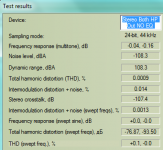
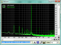
Here are some test results (no further mods yet):
1. Subjective: To eliminate the POT causing issues, I maxed the volume on the Pot and used Digital Attenuation at the source (Foobar WASAPI). Clarity improved a bit, however I noticed a loss in bass 'punch' and a slightly brighter treble (not a good thing with these headphones).
2. I ran some RMAA measurements of before & after mods. And I compared digital and Pot attenuation.
Summary: Before & after mods measurements showed nothing of interest but perhaps that's due to the free version of RMAA which has limited fourier analysis. The -10dB attenuation comparison showed large differences. Almost across the board, digital attenuation was superior. However, THD for some reason was better with the POT (which was approx 50% rotated). Note how my subjective impression above compares to the THD graph... I was perceiving additional low frequency distortion as 'punch'!
PS - The unusual frequency response measurements is due to my EQ settings which compensates for the headphone shortage of sub bass and overly bright low treble.
PSS - These measurements were done with NO gain, level matched with the EMU USB sound card, and the Sennheiser headphone driven in parallel with the external high sound card so distortion is a little higher than amp alone.
The plot shows some hum (peaks at 100Hz, 200Hz, 300Hz..) which may originate from 50Hz rectification and some ground loop.
elmura, I don't think you really understand. It isn't that the pot is causing distortion, it's that the variation in input impedance to the op amp can cause distortion. Now you have a 50K resistor (effectively) as your source impedance, which does not match the inverting input of the op amp, which is something you must do for minimum distortion. So, of course, distortion was different between full-rotation and half-rotation of the pot.
Also, why did you make your measurements with the audio EQ'd? Flat setting would tell us a lot more.
What I see is someone who puts practice before principles, and like Tesla and Edison, you may stumble upon some combination of "what works" and maybe understand WHY it works. But the real shortcut is to read the datasheet and make sure all the requirements for utilizing the chip are met. Then move on to the application notes for that family of chips and see what is recommended by the designers.
An example appropriate for this forum is one popular mod that parallels two chips where there was originally one. The advertised result is, of course, "better tone." The side effect is that the two chips work against each other, and they both get really hot. The reason is that you can't just parallel two op amps without consideration. As a result, the device draws so much current that you can no longer use it with a battery!
I suggest you put EVERYTHING back the way it was, turn up the input pot, and run your measurements with the DAC EQ set for flat. Then change one thing at a time and re-run your measurements to see what effect it had on it. Then you will be able to see if you are getting closer to your goal, or further away from it.
Last edited:
I had some time today to modify and test the results. I replaced the 10K input resistors with 4.7K to match the opamp input impedances. I don't have any 10R resistors to reduce the power rail RC filter (I did consider removing the resistor as I haven't seen it much in audio circuits). I twisted the 2 input wire pairs to reduce interference (they're not shielded). I left the input DC coupling out as the DAC DC offset measured excellent (<0.2mV probably has output caps)
The measured results showed a minor reduction in noise from 2kHz up (2dB to 5dB) plus a few less spuria at lower frequencies. The peaks at 100, 200, 300... are unchanged. Next is to find the cause of the hum (power or ground as suggested). How do I identify the cause?
THD was unchanged. IMD had a very very minor improvement (0.013% to 0.012%) and similar with IMD swept freq.
As per Mfratus request: I've taken measurements with EQ disabled and in Stereo, Pot at max. Results below (with Sennheiser headphones driven). Quite good imo
Attachments
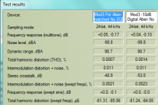
Whilst listening post mod, I noticed I found enjoyment dropped a small notch. I was listening with digital attenuation, pot at max since previous results showed such a benefit to this approach.
So I re-measured the two attenuation approaches (-10dB digital vs Pot matched level), and with this mod, the tables have turned! Now the Pot results were superior! A positive backed up with a slightly more enjoyable sound.
So I re-measured the two attenuation approaches (-10dB digital vs Pot matched level), and with this mod, the tables have turned! Now the Pot results were superior! A positive backed up with a slightly more enjoyable sound.
Attachments
removing the input cap especially in an headphone amplifier should not affect the sound. I suspect some volume pot DC interaction and impedance problems like abraxalito said, however I cant see how the impedance would be affected by removing that capacitor...
If you find the sound unclear try inserting a little feedback into this circuit
Ps. Speakers are more revealing I find and a few input/output capacitors wont change anything to the sound, (I have hd600 and Grado Rs2 among others and they sound perfectly find with any computer output!)
If you find the sound unclear try inserting a little feedback into this circuit
Ps. Speakers are more revealing I find and a few input/output capacitors wont change anything to the sound, (I have hd600 and Grado Rs2 among others and they sound perfectly find with any computer output!)
mfratus - re: your post # 25, Beyerdynamic and/or Sennheiser (can't remember which) chose the Lehmann BCL amp to partner the launch of their top of the line headphones not too long ago. That might suggest they thought more highly of it than even their own HPA offerings, which are no slouches.
Last edited:
Some updates:
1. Tried a different headphone cable, slightly improved sound but not to image depth.
2. A couple simple mods - first, a simple ground lift of the board to the chassis from 2 points: a) removed the screw that connects the filtered ground plane to the chassis then b) removed PCB from chassis to stop the Pot making chassis connection to mains Earth. These made a slight measured reduction in noise from 2kHz up. Importantly, IMD was quite improved.
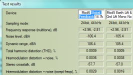
3. As many have suggested Global Feedback, I gave it a try. I disconnected one end of the 4.7k feedback resistor and soldered a 10k jumper to the output pins (after the 10R output Rs). I had high hopes for this based on so many recommendations... The result was slightly worse than point 2 above except for a slight reduction in noise! Confused. Sure, there's no capacitor to stabilise but I'm not sure if that would change any audio measurement. For reference I've attached measurements of comparison.
What do you make of this feedback mod? PS - I chose 14.7k as it was near the Pot + Input R value at high volume levels I sometimes listen.
PS - Measurements were with headphone attached, mono measurements, EQ enabled (purely comparative)
1. Tried a different headphone cable, slightly improved sound but not to image depth.
2. A couple simple mods - first, a simple ground lift of the board to the chassis from 2 points: a) removed the screw that connects the filtered ground plane to the chassis then b) removed PCB from chassis to stop the Pot making chassis connection to mains Earth. These made a slight measured reduction in noise from 2kHz up. Importantly, IMD was quite improved.
3. As many have suggested Global Feedback, I gave it a try. I disconnected one end of the 4.7k feedback resistor and soldered a 10k jumper to the output pins (after the 10R output Rs). I had high hopes for this based on so many recommendations... The result was slightly worse than point 2 above except for a slight reduction in noise! Confused.
Sure, there's no capacitor to stabilise but I'm not sure if that would change any audio measurement. For reference I've attached measurements of comparison. What do you make of this feedback mod? PS - I chose 14.7k as it was near the Pot + Input R value at high volume levels I sometimes listen.
PS - Measurements were with headphone attached, mono measurements, EQ enabled (purely comparative)
Attachments
Last edited:
I'm currently working on a headphone amplifier. Two months of engineering work are already in the process. So far I am very satisfied with my results. If you understand the job, you will get to the measured values in the PDF attachment. The values are measured at 100 ohm load. At 25 ohm they are almost identical (white = analyzer, green = headphone amp). The amplifier should be even better than measured because my analyzer is very limited.
Attachments
Last edited:
@diyralf - looking good. Are you going to post a thread on it? See if there's a way to kill that 3rd harmonic and 50Hz hum.
Further update to my mod project, I raised the total global feedback resistance to 26.7k to better match the input impedance on the non-inverting input at typical volume levels, with the benefit of reducing the headphone load on the opamp. I also kept mains Earth lifted but connected chassis to signal ground. Sound is very clean & clear, punchy bass, good imaging & soundstaging (depth is still not great), but there is a reduction in involvement factor...
Measurements are slightly improved over the previous and IMD is improved over several prior experimental mods. However, comparing current Mod7 to Mod3 finds an increase in noise (4dB) and greater high frequency IMD but otherwise good results.
The power supply hum has not been resolved and my research on this website plus testing indicates that either the power supply decoupling caps may be too far from the opamp pins, or the feedback resistor may need a Cap across it. I tried running a wire across multiple ground points to see if there was a ground loop that could be cured with no luck.
Hi elmura,
Sorry .. this is gonna sound mean, but I think directness is called for.
Sure hope you don't smoke your expensive headphones. I wouldn't connect anything decent to the amp the way you're going at this. It is very likely to oscillate ultrasonically at some point (if it isn't already) and the analyzer you're trusting doesn't have the bandwidth to detect it.
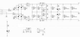
The impedance at the inverting input is substantially set by R's 15, 17, 16 and 18 (NOT R21 and R22) UNLESS both S101 and S102 are all OPEN. If that's the case, then you've created a new problem by adding a bunch more phase shift to the negative feedback. Adding global feedback is not a trivial undertaking.
The diamond buffer is extremely effective at isolating the op amp output from the headphone load. The op amp would barey notice if you plugged in an 8 ohm speaker.
Your last paragraph is pure wrong-think: Power supply decoupling caps are (usually) placed close to the op amp for high frequency stability, not hum. A cap across the feedback resistor will not affect hum either, but it will change stability and alter other qualities. 'Running a wire across multiple ground points' is only going to add ground loops and other hum possibilities. Are you absolutely sure you can hear it? Its over 80 deciBels down according to one of your FFTs.
One thing of note, noise-wise: The spec sheet gives a 40 to 1 range for the op amp's input current -- typ 5 pA, but still within spec up to +/-100 pA. Still that's mighty low to be a source of noise at these impedance levels, but maybe $4 on a replacement would be worth a try. At least it would be lower risk than some of the other things.
If you had started with a low-dollar HPA to begin with, some of these pursuits might be more reasonable. But this is a well-regarded device. How you could think the designer so foolish or incompetent as to overlook these measures, some of which would cost nothing (as if that would even matter to a high-end product), is beyond me.
Regards,
Rick
Sorry .. this is gonna sound mean, but I think directness is called for.
Sure hope you don't smoke your expensive headphones. I wouldn't connect anything decent to the amp the way you're going at this. It is very likely to oscillate ultrasonically at some point (if it isn't already) and the analyzer you're trusting doesn't have the bandwidth to detect it.
The impedance at the inverting input is substantially set by R's 15, 17, 16 and 18 (NOT R21 and R22) UNLESS both S101 and S102 are all OPEN. If that's the case, then you've created a new problem by adding a bunch more phase shift to the negative feedback. Adding global feedback is not a trivial undertaking.
The diamond buffer is extremely effective at isolating the op amp output from the headphone load. The op amp would barey notice if you plugged in an 8 ohm speaker.
Your last paragraph is pure wrong-think: Power supply decoupling caps are (usually) placed close to the op amp for high frequency stability, not hum. A cap across the feedback resistor will not affect hum either, but it will change stability and alter other qualities. 'Running a wire across multiple ground points' is only going to add ground loops and other hum possibilities. Are you absolutely sure you can hear it? Its over 80 deciBels down according to one of your FFTs.
One thing of note, noise-wise: The spec sheet gives a 40 to 1 range for the op amp's input current -- typ 5 pA, but still within spec up to +/-100 pA. Still that's mighty low to be a source of noise at these impedance levels, but maybe $4 on a replacement would be worth a try. At least it would be lower risk than some of the other things.
If you had started with a low-dollar HPA to begin with, some of these pursuits might be more reasonable. But this is a well-regarded device. How you could think the designer so foolish or incompetent as to overlook these measures, some of which would cost nothing (as if that would even matter to a high-end product), is beyond me.
Regards,
Rick
Hi elmura,
Sorry .. this is gonna sound mean, but I think directness is called for.
Sure hope you don't smoke your expensive headphones. I wouldn't connect anything decent to the amp the way you're going at this. It is very likely to oscillate ultrasonically at some point (if it isn't already) and the analyzer you're trusting doesn't have the bandwidth to detect it.
The impedance at the inverting input is substantially set by R's 15, 17, 16 and 18 (NOT R21 and R22) UNLESS both S101 and S102 are all OPEN. If that's the case, then you've created a new problem by adding a bunch more phase shift to the negative feedback. Adding global feedback is not a trivial undertaking.
The diamond buffer is extremely effective at isolating the op amp output from the headphone load. The op amp would barey notice if you plugged in an 8 ohm speaker.
Your last paragraph is pure wrong-think: Power supply decoupling caps are (usually) placed close to the op amp for high frequency stability, not hum. A cap across the feedback resistor will not affect hum either, but it will change stability and alter other qualities. 'Running a wire across multiple ground points' is only going to add ground loops and other hum possibilities. Are you absolutely sure you can hear it? Its over 80 deciBels down according to one of your FFTs.
One thing of note, noise-wise: The spec sheet gives a 40 to 1 range for the op amp's input current -- typ 5 pA, but still within spec up to +/-100 pA. Still that's mighty low to be a source of noise at these impedance levels, but maybe $4 on a replacement would be worth a try. At least it would be lower risk than some of the other things.
If you had started with a low-dollar HPA to begin with, some of these pursuits might be more reasonable. But this is a well-regarded device. How you could think the designer so foolish or incompetent as to overlook these measures, some of which would cost nothing (as if that would even matter to a high-end product), is beyond me.
Regards,
Rick
Hi Rick,
As mentioned in my early posts, I've set unity gain as I am able to listen between 12:00 and 3pm most of the time, with max volume set for Classical & other high Dynamic Range music. As alerted by mfratus, this opamp datasheet specifies that both input impedances should match. So, with the 50k Pot + revised R13/R14 (from 10k to 4.7k), that's around 27k at typical listening levels. So, to match global feedback I ran total 27k from the output to the inverting inputs. Global feedback was a recommendation by several on this thread. I have a software oscilloscope that I can hook up to the E-MU 0204 to measure phase shift & oscillation, but I've never done that so not sure how to do it.
As for the hum, it's been suggested as ground loops, and my research on the web suggested running a short between various ground points whilst monitoring the noise with a real time analyser. This didn't find the cause.
Other threads have suggested hum caused by input lead interference, power decoupling caps and need for feedback caps. The input leads are far from the trannie & twisted, and the noise was there before modding. Otherwise I'm at a loss. In the Dynamic Range measurements, there is some 50dB range from the hum peaks to the signal.
As for your last paragraph, I have been modding and creating simpler amps for years. We are obviously on different levels of thinking as I believe that most things can be improved - even a Porsche. And there are some on this and other threads who've looked at this circuit and agree that it ain't perfect as you seem to believe.
I'm open for constructive suggestions so please, if you have another way of fixing the source of hum and resolving phase shift, I'm receptive.
PS - You stated that the buffer isolates the opamp from the load, but isn't that only with the original schematic? With global feedback, isn't the opamp
seeing some headphone reactivity?
For starters, let's not spend any more time talking about hum until you install shielded input wiring. I reread the entire thread, checking every post for the -50 dB hum measurements, finding none. Please advise. The worst was 80 dB down, one was > 100 dB; both are relative miracles when there are unshielded wires less than 3 cm from the incoming AC.
Also, its probably time to check the bias of the output stage -- the 9 and 13 mV offsets listed in post #18 suggest a leaky transistor.
quote: As for your last paragraph, I have been modding and creating simpler amps for years. We are obviously on different levels of thinking as I believe that most things can be improved - even a Porsche. And there are some on this and other threads who've looked at this circuit and agree that it ain't perfect as you seem to believe.
On the contrary, I agree wholeheartedly with 'xrk971' -- this is an extremely pedestrian design, utterly uninspired, using only the MOST ordinary of components -- except for the capacitor idolatry. If your RMAA is to be believed (*1), this amp is already performing WAY above its pay grade; few of the measurements exceeded 38 Parts Per Million above sheer perfection!
Of course a Porsche can be improved, but not by removing parts with a hacksaw. And I wouldn't expect quality tips from random strangers, none of whom had driven, ridden in, or even seen the car, but instead are basing their opinions on my description of
the issues. Neither would I imagine getting a 40% horsepower increase by cutting off half the exhaust system ('so it can breath better'), or having the next-door neighbor with a Bridgeport, mill the heads ('better compression'), even though I've known people that have (to lesser cars). Instead, I would make sure my team had at least a few advanced degrees; then I'd try to wear out the mainframe with simulations -- but WAIT! These days a simulation is essentially FREE ! Please, get LTSpice or equivalent -- there are people on here willing and able to help you learn to use it -- and QUIT GUESSING ! There is no longer any reason whatsoever for idle speculation, or blown parts, or hours spent scrutinizing minute differences in FFTs and other measurements.
And now that we've come this far (hate me if you must), it would be worth trying with some gain at the op amp. Normally I would heartily avoid adding gain -- just to attenuate elsewhere. But with high impedance HP's, you may have pretty wide output voltage excursions. At unity gain, every one of those volts is required common-mode at the input, which is a major linearity challenge for any JFET input op amp, but this one in particular.
Regards,
Rick
*1) Which is suspect, at this point. Too many of these mods should have caused more change than indicated.
"or having the next-door neighbor with a Bridgeport, mill the heads ('better compression'), even though I've known people that have (to lesser cars)."
Actually, shaving a millimetre off heads is very effective at raising fuel efficiency, responsiveness, torque & top end power. The owner must then use a higher octane fuel to prevent autoignition at high loads.
And "cutting off half the exhaust system" will improve top end power at the expense of noise. Depending on the engine and the driver, the loud noise may be a good thing too. The weight reduction helps performance further.
As for the amp in question, I ended up reducing feedback resistance back to original 4.7k with the diamond buffer in the loop.
I applied a small amount of gain also (10dB)
Haven't had much time to measure but the sound is cleaner. Bass took a dive however. It seems the feedback loop is controlling bass distortion better but at the expense of some enjoyment needed with the lean Sennheiser HD800.
I found if I leave it powered up for a while before listening, the amp case warms up and with it, the bass... Possibly due to thermal drift
Last edited:
Why? Isn't it an effective means of improving PSRR at higher frequencies? What are the downsides in your experience?Dual op amp powered off RC filtered rails - double yuck
- Status
- This old topic is closed. If you want to reopen this topic, contact a moderator using the "Report Post" button.
- Home
- Amplifiers
- Headphone Systems
- Please technically explain this audible mod