Will catch you tommorrow ") just watch the connections to the FETs and get 'em the right way round.
just watch the connections to the FETs and get 'em the right way round.
As your FET's will be off the PCB make sure the resistors R18 and R21 are soldered actually on the legs of the FETs' to prevent parasitic oscillation --- very important with all power FET's.
Good luck Tibi ----it's looking good so far.
just watch the connections to the FETs and get 'em the right way round. As your FET's will be off the PCB make sure the resistors R18 and R21 are soldered actually on the legs of the FETs' to prevent parasitic oscillation --- very important with all power FET's.
Good luck Tibi ----it's looking good so far.
Mooly said:Will catch you tommorrow
As your FET's will be off the PCB make sure the resistors R18 and R21 are soldered actually on the legs of the FETs' to prevent parasitic oscillation --- very important with all power FET's.
Good luck Tibi ----it's looking good so far.
Thanks,
I'll try connecting the FETs now, I'll post the results here, hopefully I won't run into any issues.
Mooly said:Just watch the connections and watch tweaking that pot, 5 k will be very critical -- it will be all or nothing if you are not very careful-- which the FETs' won't like.
If you put a bulb in the mains lead that will save any mishaps.
Catch up with you tommorow
Progress report:
 WOW! this amp sounds wonderful!
It wasn't easy to adjust the bias because of the 5k pot, but I managed to set it by gently tapping on the screwdriver clockwise rather then turning it.
I only listened to it at a very low volume (approx 1-2V AC on the output), It's to late now to drive it any louder. Can't wait for tomorrow morning to listen to it properly.
Thanks Karl!
I'll have more info, on how the amp sounds, tomorrow.
Well done, that's excellent news.Try and get a fixed resistor installed for the pot. If you can measure the pots value as you have it set ( say it's 200 ohm ) try adding a 270 ohm across the pot and then readjust.
It will make it much less critical. The actual value of current you set is not at all critical but 100 ma is about right. The value will alter slightly as the outputs warm but with them being lateral FET's you won't get any runaway -- the bias will tend too fall rather than rise.
You will need to get hold of a relay for each channel something like,
http://cpc.farnell.com/SW01722/components-spares/product.us0?sku=tyco-electronics-schrack-rp330012
the higher the coil voltage the better 24 vdc if you can get it.
Mooly said:
Try and get a fixed resistor installed for the pot. If you can measure the pots value as you have it set ( say it's 200 ohm ) try adding a 270 ohm across the pot and then readjust.
It will make it much less critical. The actual value of current you set is not at all critical but 100 ma is about right. The value will alter slightly as the outputs warm but with them being lateral FET's you won't get any runaway -- the bias will tend too fall rather than rise.
You will need to get hold of a relay for each channel something like,
http://cpc.farnell.com/SW01722/components-spares/product.us0?sku=tyco-electronics-schrack-rp330012
the higher the coil voltage the better 24 vdc if you can get it.
Thanks for all the help, this just sounds amazing.
I haven't had time to measure the pot and get some resistors in but I will.
Now it's time to start building the other channel
Yeah I'll have to order to relays, I am reading about 10V DC on the output about 2 seconds after I unplug it from the mains (with no load attached).
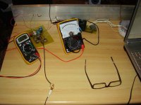
I've attached the a PIC of the amp, the FETs were already warmed up so the quiescent current has dropped to about 92 mA.
Attachments
I am pleased Tibi.
That looks a nice chunk of metal for the heatsink. Keep those leads short and direct to the FET's don't twist them together.
I can draw you something really simple for the relay driver unless you have your own ideas. You need a reliable delay at switch on of around 5 or 6 seconds and a reasonably quick off time. That's not such a problem as the PSU caps will run the amp for quite a few seconds.
Mooly said:I am pleased Tibi.
That looks a nice chunk of metal for the heatsink. Keep those leads short and direct to the FET's don't twist them together.
I can draw you something really simple for the relay driver unless you have your own ideas. You need a reliable delay at switch on of around 5 or 6 seconds and a reasonably quick off time. That's not such a problem as the PSU caps will run the amp for quite a few seconds.
Yeah, it's a 1m long heatsink, I'll have it cut into smaller pieces.
The leads will be replaced with shorter and thicker wires, the wires to the fets cross eachother since I was to lazy to remove and switch their places for testing
.Once I'll put in in a box I'll tighten everything up.
A reliable relay driver circuitry would be welcome!
Thanks.
Mooly said:
Hi Karl!
Sorry, I've been extremely busy the last couple of days, I haven't had time to work on the amp.
I have some errands to do today so hopefully I'll get a chance to drop by my supplier for parts.
Yesterday I connected the amp to a high efficiency Monitor Audio speaker and although with the previous speaker I couldn't hear any background noise I can clearly hear a radio station if I put my ear to the tweeter.
Any ideas where I could be picking up RF?
Thanks.
Tibi.
Hi Tibi,
We wondered where you had got too
Picking up a radio station, that sounds an old fashioned fault. Are you near any powerful AM transmitters ?
Have to put my thinking cap on for that.
Just off the top of my head, it's most likely being picked up on any input wiring. Is it there if you just connect say a 10K across the input and nothing else. Strange though, that 150 pf cap should stop that anyway. But try it !!
Is it possible it could enter via the speaker leads ? In the end didn't we say that we would try it without the output inductor. Maybe try a an output coil ??
It's really going back to basics with this, to be honest it's the last problem I would have suspected. Trying to think back, the cause is that the AM radio signal gets demodulated usually by the B-E junction of the input stage. Try as I say disconnecting the inputs totally and soldering a 10k or so across the inputs pads on the PCB.
Mooly said:Hi Tibi,
We wondered where you had got too
Picking up a radio station, that sounds an old fashioned fault. Are you near any powerful AM transmitters ?
Have to put my thinking cap on for that.
Just off the top of my head, it's most likely being picked up on any input wiring. Is it there if you just connect say a 10K across the input and nothing else. Strange though, that 150 pf cap should stop that anyway. But try it !!
Is it possible it could enter via the speaker leads ? In the end didn't we say that we would try it without the output inductor. Maybe try a an output coil ??
It's really going back to basics with this, to be honest it's the last problem I would have suspected. Trying to think back, the cause is that the AM radio signal gets demodulated usually by the B-E junction of the input stage. Try as I say disconnecting the inputs totally and soldering a 10k or so across the inputs pads on the PCB.
Ahhh,
Well the new speaker is definitely connected with a longer cable then the previous one so that could act as an antennae.
And yes I'm about 500m away from a local radio station's emitter.
I'll try adding an output coil.
I'll also try removing the input cable and add an R.
OK I will have a think. It's certainly ( hopefully ? ) not a major problem.
There is the faint possibility with you being so near that the component legs themselves are picking up the signal.
The base lead of the input transistor is the main suspect if that were the case. Some amps used to have a tiny ferrite bead slipped onto the leg.
Just a thought, that's the last thing to try though at the moment, let's see if we can pin down how it's being picked up.
Output coils --- must be air spaced, not very critical, say try 20 turns of enamelled copper wire ( I am useless with wire gauges -- lets say quite thick ) wound in a single layer tightly coupled.
Fit it as close to the amp outut terminal as poss.
If the problem is pickup by components etc this may all disappear if a metal case is used.
Fit it as close to the amp outut terminal as poss.
If the problem is pickup by components etc this may all disappear if a metal case is used.
- Status
- This old topic is closed. If you want to reopen this topic, contact a moderator using the "Report Post" button.
- Home
- Amplifiers
- Solid State
- please help with an oscillating amp