Without the 6l6g and with 12Ax7 in, the buzz was still there but became very very faint.keithgreenhalgh said:I doubt it a problem with the power transformer. Try pulling the 6L6 tubes and tell me if you still have hum.I have more questions for you but try this first.
Will look forward to your input.
Thanks!
The 100ufd 400volt cap conected to the 12ax7 would have about 180-200 volts on it but you said you had a 16volt cap in series with a resistor to gnd. this doesn't make sense because the cap would fail. The 100ufd 400volt cap is what gives the plate of the 12ax7 a pure d.c. voltage. without this capacitator the 12ax7 would amplifiy the hum from the power supply.Check the wiring again and If you have a voltmeter ,measure the plate voltage. It should be 180-200 volt range.Any capacitor connected to gnd generally allows a 100% greater working voltage so it should be rated at 400volts and 100ufd sounds about right for the value.
You are right, my mistake. The 100/16V cap is actually connected to the cathode of the 12AX7 not to the plate side.
So on the actual board, the cathod of 12AX7 is connected to 91K feedback capacitor as well as 1K resistor and 100/16V cap. Both of 1Kand 100/16/v are connected to ground through 1 100 ohm resistor.
The plate voltage for 12AX7 is 147V.
12AX7 plates of both channels are connected to single set of 100 / 400V and 10K ohm resistor.
Now the buzz is mostly on the left side. Right side is quite faint.
Will wait for your reply.
SY said:How are the heaters referenced to ground? Are they biased up or (as the schematic suggests) just left to float? Floating heaters = bad idea.
Put a scope on the input tube's rails and see what your ripple looks like.
The schemtic omits this but the one side of 6.3V secondary is connected to the ground. The 10V rectifier circuit for 845 heater is referenced to ground via 100 ohm hum pot and 1 ohm cathode resistor.
Wish I had a scope. May be some day....
Now the buzz is mostly on the left side. Right side is quite faint.
What did you change to cause this? It would seem that you've eliminated supply ripple as the principal culprit.
The schematic omits this but the one side of 6.3V secondary is connected to the ground.
That is the single worst way to do it. You can greatly improve things (and maybe cure your buzz?) by disconnecting that ground, connecting two equal resistors of roughly 100 ohms in series, then put the seriesed resistors across the heater winding. Their junction forms a virtual centertap. That centertap can then be connected to a +50V or so reference, formed by connecting an appropriately sized voltage divider across the B+, and bypassing the lower leg to ground.
You also want to have the heaters grounded against common-mode AC or RF by bypassing each end of the heater to the chassis through a ceramic disc cap. At minimum, do this at the input tube.
This sounds fussy, and it is, but this can make an obvious sonic difference.
The amp did it itself. It appears the buzz changes over time as amp is turned on and off.SY said:
What did you change to cause this? It would seem that you've eliminated supply ripple as the principal culprit.
By bypassing you mean, one end of ceramic cap to the chassis and the other to an end of 6.3 winding, right? So this must be done after removing the ground from 6.3 winding? What kind of capacitance value the ceramic disc cap should have?SY said:
You also want to have the heaters grounded against common-mode AC or RF by bypassing each end of the heater to the chassis through a ceramic disc cap. At minimum, do this at the input tube.
I¡¯m not sure how this works, but it seems to float the heater circuit at 50V DC from ground. Could you explain why this is better?SY said:
connecting two equal resistors of roughly 100 ohms in series, then put the seriesed resistors across the heater winding. Their junction forms a virtual centertap. That centertap can then be connected to a +50V or so reference, formed by connecting an appropriately sized voltage divider across the B+, and bypassing the lower leg to ground.
Thanks.
Does the buzz vary if you change the 12AX7?
Biasing up the heaters helps alleviate leakage between the heater and the cathode. There's a really complete and understandable explanation in Morgan Jones's "Valve Amplifiers," 3rd edition, which you ought to have.
What's important and nearly always neglected is to take care of common mode noise, which is the point of those ceramic caps. I'd put them right at the tube sockets.
Starngely enough, the buzz does not change as I change any tubes.
Thanks for the explanation on the biasing heater. What range of volotage rating and capacitance do you recommend for ceramic disk cap? Is it o.k. if I add the ceramic cap when the heater is still connected to ground?
Thanks!
Thanks for the explanation on the biasing heater. What range of volotage rating and capacitance do you recommend for ceramic disk cap? Is it o.k. if I add the ceramic cap when the heater is still connected to ground?
Thanks!
So I think I will try SY's heater circuit idea. But since the amp didn't have buzz as new, I'm hoping to first try any other idea that will help to identify a possible demaged part in the existing amp circuit. Buzz diasppeared w/o 12Ax7 input tube, but grounding the asAX7 grid didn't change buzz...
Any one?
Any one?
rdk845 said:So I think I will try SY's heater circuit idea. But since the amp didn't have buzz as new, I'm hoping to first try any other idea that will help to identify a possible demaged part in the existing amp circuit. Buzz diasppeared w/o 12Ax7 input tube, but grounding the asAX7 grid didn't change buzz...
Any one?
Like you said,amp didn"t have buzz when it was new so why should you have to change the design.It doesn"t make sense.
Im out of ideas.What about taking it to a repair shop? At this point it makes more sense than redesigning the amp. Please Post The final result so we will know in the future. thanks Keith
")
ground to chassis
I found that somehow the chassis is connected to circuit ground. Is this normal? If not, could it be the source of buzz?
I don't see any point on the board that the circuit ground is intentionally connected to chassis, so it could be connected through transformer. The schematic shows that the main earth is not to connected to anything and this is the case for the amp.
Thanks.
Especially with heater-cathode voltage issues, buzzes can suddenly appear or disappear (power line is dirty). But if changing input tubes didn't do it, my bypassing/heater biasing suggestion won't fix the problem, though it will prevent future ones and potentially clean up the amp's sound. The value of the common-mode bypass caps isn't critical. 10nF 600V discs are cheap as dirt and work fine.
For the next repair step, I'd go simple and resolder/tighten every connection between the input stage and ground, then tighten every mechanical ground or voltage supply connection for the power supply.
Connecting signal ground to chassis is not unusual (as long as it's done at only one point), but not optimal, either. Again, I'd recommend reading Morgan Jones's treatment of grounding in tube amps in "Building Valve Amplifiers."
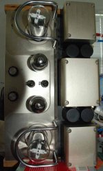
Finally, do you have some photos of the amp, preferably top and bottom? I wonder if there isn't something obvious we're overlooking...
For the next repair step, I'd go simple and resolder/tighten every connection between the input stage and ground, then tighten every mechanical ground or voltage supply connection for the power supply.
Connecting signal ground to chassis is not unusual (as long as it's done at only one point), but not optimal, either. Again, I'd recommend reading Morgan Jones's treatment of grounding in tube amps in "Building Valve Amplifiers."
Finally, do you have some photos of the amp, preferably top and bottom? I wonder if there isn't something obvious we're overlooking...
SY said:
For the next repair step, I'd go simple and resolder/tighten every connection between the input stage and ground, then tighten every mechanical ground or voltage supply connection for the power supply.
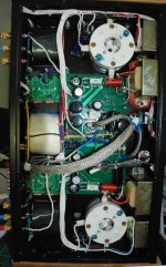
Will try this. Meanwhile here are the photos.
Attachments
bottom
Bottom view.
the gray cable in the middle is from input RCA to input selector and these are bypassed. Actual input cable is connected from 1 set of RCA directly to 100K pot then to input tubes. These are shielded. Right hand side from top to bottom, we have a choke, left and right interstage trannies then another choke. The white/blue cables from board to 8 ohm cables have 91k feedback resistors in them.
If you request some close-ups, I will post.
Thanks for your help.
Attachments
I like sy.s idea of a dirty a/c line into the amp. It is not that uncommon to have interference come in on a A/C line. This would explain it coming and going.This would also explain why it was fine when you got the amp but now has intermittent hum.Dirty A/C line voltages are usually caused by a nearby factory with large equipment.Do you live near an industrial area? Can you take the amp to a friends place in a different part of town or even a different town to see if the buzz goes away.I know they have power filters for computors but I don't know if this would work on your amp,perhaps sy might know. Most amps don't have filtering for lines because it requires extra components and extra expense and they want to keep the cost down and also its not needed on 95% of amps anyway.My idea is easy to try and doesn't require any rewiring of the amp.Give it a try,you never know!
I have a couple of other amps, which are dead silent in the night. But this amp buzzes exactly same way for night and day in same day. Buzz some times changes as I turn on and off many time over many days. Also if it is AC, I wonder why left side buzzes much larger than right side.
But at some point, I will try to move the amp and test in a different part of town. (my work place)
But at some point, I will try to move the amp and test in a different part of town. (my work place)
- Status
- This old topic is closed. If you want to reopen this topic, contact a moderator using the "Report Post" button.
- Home
- Amplifiers
- Tubes / Valves
- Please help me in getting rid of the buzz.