Hi - interested to know if anyone still monitors this thread about the Playmaster Series 200 amplifier. Made mine soon after the Dick Smith kit became available in 1985, and still it is a wonderful centrepoint of our entertainment system. Only became inoperative once, when a power supply electrolytic blew.
Can anyone help with sourcing the McMurdo DPST switch used for muting the volume circuit? Mine is very scratchy and contact cleaner doesn’t fix it.
Also interested in the remote volume control possibility -“aftersmoke”, did yours work?
Thanks,
Peter
Photo of front of amplifier showing the MUTE switch:
Oh Wow you still have the Original power switch as well! Mine died years ago and I replaced it with a rocker switch. I'd forgotten what the original looked like.
My mute and mono switches died (actually disintegrated) many many years ago, I never actually replaced them, because I couldn't find anything that would fit the holes...
Mine is still the main amp in my system, but the entire preamp is now bypassed (the pic a bit earlier in the thread of my B1/synergy crossover acts as the "pre-amp"..
Tony.
It's been a long time since I looked, thought I'd try again. found this https://au.mouser.com/ProductDetail...tch/A205J61ZQ0004?qs=dzIVSDEasnvK/YGCL7t9xw== which possibly with some blocks the right size could be made to fit. Would depend on whether the paddle will fit through the existing hole and it's vertical movement though. Not sure if possible to work out from the diagrams if it would work before purchasing...
The thing to search for is paddle switch, toggle switch gives too many of the normal threaded type switches.
Tony.
The thing to search for is paddle switch, toggle switch gives too many of the normal threaded type switches.
Tony.
Hi All
Apologies I've been registered for a long while but this is my first post..I think!
Hopefully some may still look at this thread.
I'm seeking help. I have 2 Playmaster 200 amplifiers and can't find circuit info or schematics. After a bit of work I have both going...kind of. I can't get the relays to switch on however the amplifiers work I have bypassed the relays and they play and sound fine. The DC offset is less than 40ma on each channel (after changing the long tailed pair input transistors) I'm wondering if the protection? relay switch circuit is faulty but not knowing how it works makes it difficult to diagnose. Oddly both amplifiers seem to have the same problem.
Many thanks and regards")
Apologies I've been registered for a long while but this is my first post..I think!
Hopefully some may still look at this thread.
I'm seeking help. I have 2 Playmaster 200 amplifiers and can't find circuit info or schematics. After a bit of work I have both going...kind of. I can't get the relays to switch on however the amplifiers work I have bypassed the relays and they play and sound fine. The DC offset is less than 40ma on each channel (after changing the long tailed pair input transistors) I'm wondering if the protection? relay switch circuit is faulty but not knowing how it works makes it difficult to diagnose. Oddly both amplifiers seem to have the same problem.
Many thanks and regards
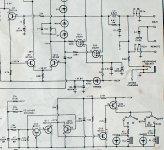
I decided to have a look, but I can't find my original copy of the kit instructions, but I did find a scan I had done of the main circuit diagram. Attached is the relevant bit for the speaker protection.
Tony.
Tony.
Attachments
Last edited:
Many thanks. The speaker switch was a problem, both Deoxit and re-solder legs needed, as well as a transistor, BC327, that had legs shorted in a previous repair by someone. The copper pads are very close, quite large but close; I finally found it and now I have one of the units going. It has had previous repairs and some track has been repaired with wire jumpers.
I believe these units sound good but the case work leaves a lot to be desired. Potentiometers are not secured on front panel and removing the bottom to work on them is a ...nuisance! I'll now have a listen and decide if further work needed, caps? etc.
Thanks for the help, now for the second unit.
I believe these units sound good but the case work leaves a lot to be desired. Potentiometers are not secured on front panel and removing the bottom to work on them is a ...nuisance! I'll now have a listen and decide if further work needed, caps? etc.
Thanks for the help, now for the second unit.
- Home
- Amplifiers
- Solid State
- Playmaster Series 200 Circuit