no. It's a tested and proven Disconnecting Network that allows fault current approaching kA to flow to Safety Earth and rupture the mains fuse quickly in event of catastrophic mains wiring damage.Westerp said:Just love that 'earth circuit' for frying diodes and creating some heat
Guess that it might even start acting as a am transmitter under certain circumstances
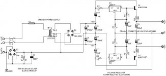
Just remove the direct wire link next to the 100nF cap (c1), or change that link to a switch.
Alright. I've made the changes as I believe they were meant to be.
1. added C10 and C11 as stabilizing caps for the regulators. It looked to me as if the other legs were protected
2. removed the direct wire link on earth circuit and moved chassis earth connection. I went back and looked at nuuk's power supply tutorial and I had definitely drawn it wrong. I thought at the time that I was copying it verbatim. I guess I will have to go even slower and triple check everything.
3. I think it might be close this time!
Attachments
jman 31 said:I am a much better contractor than I am electronics guy!
hello.
have a look at c10 and c11............
probably you thougt about connecting the +pole of the elcap c10 to pin 3 of the lm317 and the - pole to ground ......
and with c11 the other way round...........
greetings...........
Hi jman,
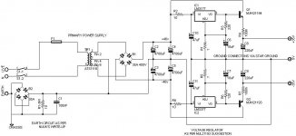
Looks good. AndrewT was right on the value for R6 - I didn't check my schematic before I posted it. You'll want to make R3 the same though, or you'll have different voltages at the rails.
Your C10 and C11 are not strictly necessary if your filter caps are close to the regulators. They won't hurt though.
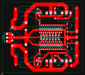
Here's the one I'm using for my lab supply. It uses a 2 pole, 6 position rotary switch to select common voltages from +/-5V to +/-30V.
Looks good. AndrewT was right on the value for R6 - I didn't check my schematic before I posted it. You'll want to make R3 the same though, or you'll have different voltages at the rails.
Your C10 and C11 are not strictly necessary if your filter caps are close to the regulators. They won't hurt though.
Here's the one I'm using for my lab supply. It uses a 2 pole, 6 position rotary switch to select common voltages from +/-5V to +/-30V.
Attachments
MJL21193 said:Hi jman,
Looks good. AndrewT was right on the value for R6 - I didn't check my schematic before I posted it. You'll want to make R3 the same though, or you'll have different voltages at the rails.
Your C10 and C11 are not strictly necessary if your filter caps are close to the regulators. They won't hurt though.
Here's the one I'm using for my lab supply. It uses a 2 pole, 6 position rotary switch to select common voltages from +/-5V to +/-30V.
Thanks man. I appreciate you giving me a starting point. I had looked at several power supplies, but none was exactly like my situation. I don't know enough about this stuff yet to mix and match with any degree of confidence.
I was thinking that r3 would need to be the same. Thanks for clearing that up for me.
I want to thank everyone for their willingness to help. Especially Pacificblue, AndrewT, MJL21193 and mjf. Maybe I can finally get started on the board now.
Jman
hello jman.
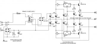
i think there is a little flaw in the schematic post 17.
the + pole of the muting elcap cm 22uf should be connected to ground.please have a look at the datasheet of the lm 3876 (e.g. www.datasheetcatalog.com or so.........).
greetings.......................
i think there is a little flaw in the schematic post 17.
the + pole of the muting elcap cm 22uf should be connected to ground.please have a look at the datasheet of the lm 3876 (e.g. www.datasheetcatalog.com or so.........).
greetings.......................
I don't consider myself anywhere near qualified to get into this argument, but after looking at the DATASHEET I think mjf may have a point on this one. I think he is saying that the schematic and the PCB are both drawn wrong!
The Cm cap coming from pin 8 on a bipolar supply (according to the datasheet) is drawn with the polarity the other way around. Unless I'm full of it and Cm is not the mute cap!
The Cm cap coming from pin 8 on a bipolar supply (according to the datasheet) is drawn with the polarity the other way around. Unless I'm full of it and Cm is not the mute cap!
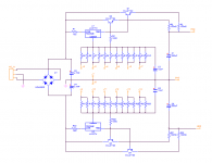
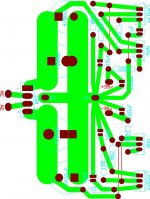
I designed a PSU layout for this project. I am not certain about the size of the traces or the ground layout. If anyone care to comment on it I would appreciate any feedback. If I have routed something wrong, or done a no-no on power supplies, whatever, please let me know.
Thanks,
Jman
PS. Maybe someday I will have enough experience to actually help someone on this site instead of always leeching, but I sure appreciate all the help and comments.
Thanks,
Jman
PS. Maybe someday I will have enough experience to actually help someone on this site instead of always leeching, but I sure appreciate all the help and comments.
Attachments
Hi jman,
The 10 ohm and 0.1 ohm resistors need to be 5 watt - you may want to layout a bit bigger than you've allowed.
Check over the pin-out for the LM's - they are different.
Calculate the current requirements of the amp this will power - you may be safer adding another pass transistor. These carry the bulk of the current and will get HOT so you'll need to put this on a pretty good heatsink.
Traces are only as good as their weakest point. The big fat trace at the smoothing caps thins to ~2mm(?) to deliver the same amount of current.
For reference, here's the layout I did for my lab supply. It is about 4 inches square with the regs and pass transistors on opposite sides, on the bottom of the board. It mounts flat on a fairly large heatsink.
Attachments
Hi J,
the stability caps around the 317/337 are still missing.
There is room around the 10uF caps ensure that 220uF can be fitted here. It will make the regulator better when you are ready to experiment.
The 4700uF caps have a lot of space around them. Do 10mF fit here?
Add fillets to any right angle corners in your traces.
Allow for different pin pitches of all the capacitors. They vary a lot.
Thanks guys,
AndrewT,
I guess I don't understand what you are talking about with the stability caps..... I added the 47uF caps but the other pins seemed have a cap at each one of them. I wasn't sure what else to add or what size they need to be. I don't know where the 220uF caps that you mentioned would go. As far as the 4700uF caps were concerned, I will have a lot of room in the case so I wasn't to worried about getting it to tight. I was planning on using some caps I already had. 7200uF's for the first ones and 4700uF for the second ones.
Thanks for the advice on the cap pin spacing. That should be an easy fix.
mjf,
I will go over those pins. I thought I had them right, but I've been known to make a mistake or ten.
MJL21193,
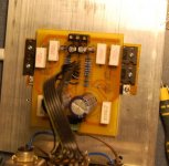
I was trying to line up all of my regulators and power transistors to attach to one big heat sink. I didn't quite understand how you heat sink yours the way you have them laid out? Do you have a photo I could look at?
I will have a look at those resistors. Do you know right off hand what the common spacing on a 5 watt resistor would be?
Once again fellas, thanks for all the help!!
AndrewT,
I guess I don't understand what you are talking about with the stability caps..... I added the 47uF caps but the other pins seemed have a cap at each one of them. I wasn't sure what else to add or what size they need to be. I don't know where the 220uF caps that you mentioned would go. As far as the 4700uF caps were concerned, I will have a lot of room in the case so I wasn't to worried about getting it to tight. I was planning on using some caps I already had. 7200uF's for the first ones and 4700uF for the second ones.
Thanks for the advice on the cap pin spacing. That should be an easy fix.
mjf,
I will go over those pins. I thought I had them right, but I've been known to make a mistake or ten.
MJL21193,
I was trying to line up all of my regulators and power transistors to attach to one big heat sink. I didn't quite understand how you heat sink yours the way you have them laid out? Do you have a photo I could look at?
I will have a look at those resistors. Do you know right off hand what the common spacing on a 5 watt resistor would be?
Once again fellas, thanks for all the help!!
jman 31 said:
I guess I don't understand what you are talking about with the stability caps.....
These are Vin to ground. You have the 47uF caps there but like I said earlier, they are not really needed if your filter caps are close to the regs.
jman 31 said:
Do you have a photo I could look at?
Do you know right off hand what the common spacing on a 5 watt resistor would be?
25mm for the wirewound ceramic cheapies.
A picture? You got it...
Attachments
- Status
- This old topic is closed. If you want to reopen this topic, contact a moderator using the "Report Post" button.
- Home
- Amplifiers
- Chip Amps
- Playback Amp