Hi All,
After dragging my feet for a few years (I've been busy) I've finally decided to build myself a headphone amp. I'm planning on a TPA6120A2 amp, and I've already looked at what Per-Anders and others have done, but I have some questions about the design:
Everyone seems to use an inverting input, and Per-Anders wrote that this is done to reduce distortion by a factor of 10. I've read the datasheet, but I don't understand how he comes to this conclusion. What have I missed? I do guess that it would be easier to build it as inverting as there'd be no need for a bias balance resistor between +in and GND.
Looking at the graphs for SNR, would it make the most sense to run the TPA6120A2 at a gain of 2.5-3 to maximise SNR? Some other designs seem to run it at a gain of 1 though, is there a good reason for this?
Finally, when putting in a top ground plane, what's the minimum distance I should have between the edge of the plane and signal traces?
TIA for the help...
I use it non-inverted with a TLE2426 and OPA690 as ground channel. To cure the DC-offset I use a servo circuit. It sounds sweet, but it's not a miracle drug.
Why use TPA6120 with input buffers? You'll get two degrading stages. An OPA2134, AD8620 or AD8066 or many of the other common opamps used for audio, drives most headphones with no problems. If you just want to buffer an opamp, you'll get a better sonic result with a common discrete "diamond buffer" in closed loop with your favourite opamp.
Why use TPA6120 with input buffers? You'll get two degrading stages. An OPA2134, AD8620 or AD8066 or many of the other common opamps used for audio, drives most headphones with no problems. If you just want to buffer an opamp, you'll get a better sonic result with a common discrete "diamond buffer" in closed loop with your favourite opamp.
nelsonvandal said:Why use TPA6120 with input buffers?
Because the TP6120 is a CFA (current feedback amp) the inverting input has a rather low impedance that can be difficult for most sources to drive, hence the use of input buffers.
This is a general rule and the distortion will be reduced, not always by 10 maybe but some. In this case hardly important since the distortion is ultralow when it's "high".Lucien said:Everyone seems to use an inverting input, and Per-Anders wrote that this is done to reduce distortion by a factor of 10.

This is dependent of how you'll do the pcb. Boards like mine have 12 MILS (0.012") as clearance.Lucien said:Finally, when putting in a top ground plane, what's the minimum distance I should have between the edge of the plane and signal traces?
TIA for the help...
Thanks for the comments guys. Yes, the low input impedence is why I'm putting a buffer ahead of the TPA6120. I'll probably start with the AD8610. This being my first headphone amp, there's lots of different things to try out.
Per-Anders,
I'm afraid I don't understand what you mean by"ultralow when it's "high"". But it seems I will be going for an inverting setup, so it doesn't matter anyway.")
And for the PCB clearance, I'm using EAGLE and can configure how much clearance to give between trace and plane. There's going to be a tradeoff, and I understand ground planes are usually added for stability, but in this case the extra capacitance would degrade performance.
Curious, but has anyone tried to put the input buffer op-amp in an inverting configuration as well?
Per-Anders,
I'm afraid I don't understand what you mean by"ultralow when it's "high"". But it seems I will be going for an inverting setup, so it doesn't matter anyway.
And for the PCB clearance, I'm using EAGLE and can configure how much clearance to give between trace and plane. There's going to be a tradeoff, and I understand ground planes are usually added for stability, but in this case the extra capacitance would degrade performance.
Curious, but has anyone tried to put the input buffer op-amp in an inverting configuration as well?
I'm afraid I don't understand what you mean by"ultralow when it's "high"
I think he means that even at the 6120's highest distortion level, it still measures "low" by comparison to others.
It was a relative statement.
Mr Jung never mention the words "sound", "sonic", "timbre" etc. Is this a theoretical benefit with better measured performance, or is it supposed to sound better? I've tried to buffer opamps with other opamps in many different combinations. I've always found a single opamp to sound superior, unless there's too low output current and audible distortion. Opamps do color the sound. Two opamps color it more than one. But it's probably a matter of taste. I prefer an uncolored sound.jcx said:read Walt Jung's Op amp Applications chapter on line driver/composite op amps for a differnt view - high quality input op amps with high speed high current cfa op amps providing added gain and buffering inside one feedback loop improve the character of Both amps
A diamond buffer in closed loop (Jung multiloop or simple common loop) sounds better to my ears, less colored, is cheap, easy to work with and can be made quite small. TPA6120 is not the amp that makes everything else obsolete even though it has a nice sound signature. It definately adds a coloration - silky and smooth.
multiloop operation can improve measurable characteristics - the input amp doesn't have load current issues driving the noninverting input of the output amp, maximizing the input op amp gain and linearity - the input op amp can have separately filtered supplies, the simple fact of higher loop gain also increases psrr
the output amp inside the feedback loop of the input amp is corrected for errors from noninverting drive and thermal modulation, both of which it cannot itself correct since they cause error in the input differencing operation
I think the majority of "opamp sound" discussions are suspect - there may be noticeable differences in noise, clipping behavior or psrr/interference rejection in differing circuit implementations but if the pro "Golden Ears" at Stereophile couldn't tell a tweaked Carver amp from a expensive tube amp driving speakers with large impedance variations:
http://www.diyaudio.com/forums/showthread.php?postid=152392#post152392
I don't know why I should readily believe competently implemented op amp headphone amps really have different "sound" into very benign dynamic headphones loads attributable solely to op amp manufacturer rather than overall amplifier frequency response and output impedance - when used in their linear operating limits and subjectively compared under properly controlled conditions; blind and level and frequency response matched to 0.1 dB
I do however choose to design for lowest possible distortion and large output Voltage and Current headroom - not something many common single op amp only headphone amplifiers can achieve with low impedance phones - but which multiloop TPA6120 or other buffer in loop types can
http://www.diyaudio.com/forums/showthread.php?s=&threadid=45794&highlight=
1 cm2 copper on both sides creates approx. 3 pF.Lucien said:There's going to be a tradeoff, and I understand ground planes are usually added for stability, but in this case the extra capacitance would degrade performance.
High distortion from a TPA6120 is not very high and in inverting mode the distortion will be lower.Lucien said:I'm afraid I don't understand what you mean by"ultralow when it's "high"". But it seems I will be going for an inverting setup, so it doesn't matter anyway.
Maybe we are sensitive to different kinds of coloration. In an amp with a split battery ground, I can't for my life hear any difference at all between different caps. I can't hear the difference with, or totally without caps (between rails or from rails to ground)! I can't hear the difference between using an input resistor or no resistor at all. I can't hear any difference when changing the supply voltage to the opamps (within their spec's).jcx said:
I think the majority of "opamp sound" discussions are suspect - there may be noticeable differences in noise, clipping behavior or psrr/interference rejection in differing circuit implementations...
But I can certainly hear the difference between different opamps, and the sound signature of them is exactly the same no matter what topology I use - stand alone, opamp buffers, single loops, multi loops, discrete buffers etc.
I can also hear differences in different ground/current return. TLE2426 being better than a resistor/cap divider. High quality opamp or discrete amp being better than TLE2426. Split battery ground being better than any amp.
Well, the diamond buffer might be interesting to try, but that would be something for later on.
For me, I don't just want to build the amp, I also want to have a good idea of how it works. Unfortunately analogue electronics is not my strong point. So to start, I figured I'd go for a op-amp based unit. Also, I want this to be SMD as far as possible, as I find it easier to work with.
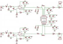
I've finally finished my initial schematic, which probably looks very familiar to most of you.
The decoupling caps are 0.1uF X7R ceramic paralled with a 1.0uF film cap. I'd prefer 0.1uF NPO/C0G ones, but first I'd have to find suitable ones.
I haven't decided yet if I'm going to have seperate voltage lines for left and right channels. I may probably do so as I alway have the option later of powering both from the same source. And the source isn't on the diagram as I figure I won't be able to fit it on the same board.
Not show (not added yet) are additional power capacitors, I'm thinking 47uF OS-CON.
For me, I don't just want to build the amp, I also want to have a good idea of how it works. Unfortunately analogue electronics is not my strong point. So to start, I figured I'd go for a op-amp based unit. Also, I want this to be SMD as far as possible, as I find it easier to work with.
I've finally finished my initial schematic, which probably looks very familiar to most of you.
The decoupling caps are 0.1uF X7R ceramic paralled with a 1.0uF film cap. I'd prefer 0.1uF NPO/C0G ones, but first I'd have to find suitable ones.
I haven't decided yet if I'm going to have seperate voltage lines for left and right channels. I may probably do so as I alway have the option later of powering both from the same source. And the source isn't on the diagram as I figure I won't be able to fit it on the same board.
Not show (not added yet) are additional power capacitors, I'm thinking 47uF OS-CON.
Attachments
0.1 uF is too high a value to find in NP0/C0G dielectric
I'd likely use 10-50 uF Al electro bypass for lower audio Z and have useful hf damping from the small esr - polymer dielectric caps reduce the esr but some damping in the ps can be good, possibly the solid dielectric could be less microphonic - an obscure concern that the Japanese audiophiles in particular have siezed on
elsewhere I commented on 6120 ps pins:
TPA supply pins are not exactly "independent"
V- are shorted internally and "A" V+ must always be on, with power to the "B " side V+ being optional
combining these constraints with ps gnds connected together and with 2 ps you still want current sharing resistors on V-, probably anti-parallel diodes across the 2 ps V+
jcx,
True. I'd read about the connected V- and then forgotten about it. So no point having separate V- supplies. I don't understand how the anti-parallel diodes across V+ would work though. Could you provide a rough sketch?
Since I'd use both channels in the chip, I don't need to worry about powering/not powering the right/wrong channel. One plus point.
0.1 uF NP0/C0G parts do exist. Unfortunately I've only seen them in 1206 size, and they're not cheap. I wonder about the quality of the 50V ones I have as they don't seem to be available anymore... Top end I can get now is 25V.
Yes, having some ESR in the PS decoupling caps is a good thing, only thing is how much? My existing plan was 0.1uF NP0/C0G + 1.0uF PPS(?) film + 47uF OS-CON + 820uF Panasonic FM. But looking back, ther's little to no ESR in that combination, especially after paralleling. Perhaps a cheaper Al electolytic on the PS... any recommendations?
Also, since I don't have space for the PS on the same board, and was going to tackle that next, I don't really have a solid plan for the PS design.
nelson, do you mean C1 and C11? They're part of the high pass filter as I want to avoid as far as possible any DC on the output.
Would it be feasable to drop the AD8610 and somehow balance the input bias currents? With the DC blocking caps there'd be isolation between the source and the TPA inputs.
Comments welcome...
The power supply? Of course.
But I don't think I can easily get hold of the same parts that you use. Specifically the capacitors. And since I am sourcing parts and drawing the schematic and layout, I'm considering things like whether to go for single or dual transformers, which voltage regulators, how to pick a varistor, etc, etc.
The dropping of the AD8610 is only a thought at this point in time, it's another one of those "something for later" things.
- Status
- This old topic is closed. If you want to reopen this topic, contact a moderator using the "Report Post" button.
- Home
- Amplifiers
- Chip Amps
- Planning a TPA6120A2 amp. Need advice