<snipped>
I fear that DC current-based measurements may lead us astray, depending on what we think we'll learn from them. Resonances within the driver's bandwidth (or even outside that bandwidth if driven acoustically, as Bolserst pointed out) are likely to lead to larger displacements than the rest of the frequency range and DC measurements won't reflect that effect. I think AC signals will be necessary to measure displacement limitations. I do agree an adjustable diaphragm-to-magnet distance would be handy. I hope to build a system with interchangeable spacers for that reason.
Thanks again for the links.
Few
Concur.
I've come up with a promising way of stacking Fiskar rotary cutting blades, spaced with fender washers, with the purpose of cutting conductors with uniform width and spacing. A whole array of ten parallel conductors can be cut in one swipe. The prototype is ugly but quick tests suggest the approach has merit. Too bad the rotary blades are priced as if they were made of platinum.
Does anyone know how wide the Magneplanar quasi-ribbon midrange drivers are in, say, the 3.7? I haven't been able to dig that up despite multiple web searches. I'm not intent on duplicating their dimensions but they would provide useful baselines.
Also, the online owner's manual for the 3.7 doesn't specify the crossover frequencies. Does anyone happen to know what they are?
Thanks for any info you can provide.
Few
Last edited:
This interesting example of a central tweeter in a planar magnetic system just popped up in another diyAudio thread. I thought I'd cite it here in case others have an interest in the original point of this thread. It's clearly different from the tall narrow aspect ratio I'm pursuing, but their design suggests the intermodulation distortion discussed earlier in this discussion was deemed to be a concern.
I'm looking for the width of the entire midrange diaphragm. I'm guessing it's something like 3" but that's based on absolutely nothing.
I've posted a similar question at the Planar Circle but haven't gotten any nibbles yet.
The Planar Speaker Asylum (and Magnepan Users Group) is at:
The Planar Speaker Asylum
I think that just the QR foil tweeter section on my Magnepan MG-12/QR speakers is at least that wide (I'm TDY at the moment and can't check). I would have to guess that a mid-range would be wider. But I could be wrong.
Last edited:
In order to make it easier to compare the magnetic field's strength, orientation, and homogeneity for different magnet spacings I drew up a FEMM model with three different spacings. I'm still using NdFeB magnets that have 1/4" x 1/4" cross sections. The attached figure shows magnet spacings of 1/2", 3/8", and 1/4" (reading from the left to the right side of the diagrams).
I also calculated the absolute value of the component of the field strength that actually moves the diaphragm---the component of the field that lies parallel to the diaphragm. I assumed the diaphragm and conductors would be 1/8" above the faces of the magnets. The upper graph shows the result.
It's interesting to see the saddles in the graph for the 1/2" spacing case (left end of the diagram). That means that near the edges of the magnets the field lines aren't oriented in the right direction, but they're so closely spaced that the desirable component of the field is still largest there.
For the sake of argument, let's assume 1/4" wide conductors. My take on the upper diagram is that you're better off fitting two runs of those conductors above magnets spaced by 1/2" rather than a single run over the 1/4" gap. The field strength in the 1/2" case is more than half of what it is in the 1/4" case, and by doubling the conductor length you get double the force. There's also a larger radiating area. All this adds up to higher sensitivity and more acoustically open area behind the diaphragm. Can anyone confirm or shoot down this reasoning? I realize some method for ending up with the same impedance in both cases will be necessary in order for this simple analysis to apply. I'm also working with a fixed number of magnets, in order to compare approaches with similar cost.
I hope the graphs make some sense...
Few
Hi Few I hope you are still here...
Can you clarify what you mean by the two conductor VS one conductor situation. How can the spacing be different, is there a picture?
I asked myself the question about multiple conductors VS a single conductor.
What exactly happens? If it is a serial conductor the impedance will get bigger
which might be good, the mass will get bigger too.
What about the driving force? Compare one conductor VS a quadruple loop which gives four conductors over the same length of magnets.
What will happen now with the driving force?
Another question, how will an iron plate influence the field strength of the magnets and what if we make -your- magnets 1/8 inch thick?
Edmund
I have built a number of prototypes in the past to work these ideas. A tru curved panel plainer magnetic,a segmented mutiple flat sections curved panel, two way with MRT mounted between two bass panels, and two way with MRT mounted centered on the same diaphragm as the bass panels. These have all been built using foils from 4 micron to 24 micron and mylars the same. Yes Ive been a busy boy ")
The best was the two way with the MRT mounted in the center between two bass panel.
The curved panels with no xovers have their merits ( espscially the 4 micron version BUT in the end the compermises to bass performance, directivity, freq response, sensativity etc IMO are trumped by a well design 2 way where the indavidual drivers can be optimized better. These drivers are well behaved and with simple xovers and concentric MRT the presentation is very close to single driver but better in a number of ways so it wins in the end. BTW this layout was consistantly less "bright" than the typical layout as in Apogee with MRT to the side reguardless of freq response tayloring.
BTW just a heads up, the higher mass diaphragms such as Apogee and Magnaplainer very much need the acustic resistance of the magnets and perf steel out back. About 12 % open area works well. Its a way to damp the diaphragm.
Last edited:
Hi Few I hope you are still here...
Can you clarify what you mean by the two conductor VS one conductor situation. How can the spacing be different, is there a picture?
I asked myself the question about multiple conductors VS a single conductor.
What exactly happens? If it is a serial conductor the impedance will get bigger
which might be good, the mass will get bigger too.
What about the driving force? Compare one conductor VS a quadruple loop which gives four conductors over the same length of magnets.
What will happen now with the driving force?
Another question, how will an iron plate influence the field strength of the magnets and what if we make -your- magnets 1/8 inch thick?
Edmund
Hello Edmund,
I'm still on the right side of the turf, as the old saying goes. I don't have a drawing handy (I can make one later if it turns out to be necessary). It's been awhile, but I think the point was that I could use closely spaced magnets with a single conductor in the magnet gap, or use a wider magnet gap that would accommodate two conductors. The magnetic field strength is smaller in the wide-gap case but you make up for it by having a BL product (field strength times length of conductor) that is twice as large. In fact, I had concluded you more than make up for it for the two cases I was comparing.
In general the driving force depends on the product B x L as described above. Using parallel rows of magnets, widely spaced, reduces B (the magnetic field) but makes room for more runs of the conductor, which increases L. You have to look at both parameters to decide where the sweet spot is for your application.
To get the impedance of the speaker within a useful range you can use various combinations of conductors in serial and parallel. Since posting those old posts my attention has turned to cutting conductors with a Silhouette computer-controlled cutter. I'm planning to stack vertically several shorter drivers, each of which has somewhere between 3 and 5 conductors in the magnet gap. I'll then use parallel and series connections of drivers to reach a target impedance.
Of course there's more to worry about than B and L. There's the directivity pattern, which is determined primarily by the driver's dimensions and whether it's used open-backed or mounted in an enclosure, the power handling, the sensitivity, the bandwidth... Lots to think about!
Few
there is a reason why magnepan uses seperate wires and places the tweeter section close to the spacers. since there is not much movement there, and it allows for thicker magnets to be used in that section to get higher efficiency without slapping into the magnets. (and thus limit the width needed to create a certain amount of ouput)
You actually loose sensativity with multi conductor runs. Yes its nessasary on the smaller drivers to get the ohms up to resionable level BUT for a given resistance it only goes down with more runs.
BTW the mag field that moves the diphragm is not just the field parallel to the conductors plane. Even the curved sections of the field are doing quite a bit of work. The force vector is not perpendicular to the diaphrgm but its still in a direction to do usefull work in that direction. In fact this can actually be seen even in distortion measurments if using wider magnets such as Apogee with wide conductor runs. On the same magnet array if u used thinner conductor traces where less of the diaphragm was driven the distortion goes up. Best with wide magnets as this to cover most of the diaphragm with conductor. Smaller magnet size design as in Magneplaner its not as important as the conductors are closer together with less undriven diaphragm.
BTW the mag field that moves the diphragm is not just the field parallel to the conductors plane. Even the curved sections of the field are doing quite a bit of work. The force vector is not perpendicular to the diaphrgm but its still in a direction to do usefull work in that direction. In fact this can actually be seen even in distortion measurments if using wider magnets such as Apogee with wide conductor runs. On the same magnet array if u used thinner conductor traces where less of the diaphragm was driven the distortion goes up. Best with wide magnets as this to cover most of the diaphragm with conductor. Smaller magnet size design as in Magneplaner its not as important as the conductors are closer together with less undriven diaphragm.
Last edited:
You actually loose sensativity with multi conductor runs. Yes its nessasary on the smaller drivers to get the ohms up to resionable level BUT for a given resistance it only goes down with more runs.
BTW the mag field that moves the diphragm is not just the field parallel to the conductors plane. Even the curved sections of the field are doing quite a bit of work. The force vector is not perpendicular to the diaphrgm but its still in a direction to do usefull work in that direction. In fact this can actually be seen even in distortion measurments if using wider magnets such as Apogee with wide conductor runs. On the same magnet array if u used thinner conductor traces where less of the diaphragm was driven the distortion goes up. Best with wide magnets as this to cover most of the diaphragm with conductor. Smaller magnet size design as in Magneplaner its not as important as the conductors are closer together with less undriven diaphragm.
magnets are positioned that the gap will be in between the rows of magnets. it is a miss conception that the field is above the magnets. If you would use big magnets there would be less gaps to place the wires in (above). and multiple wires are used to increase resistance but most of all increase power handling.
at the tweeter area they used even smaller but thicker magnets. to increase driven area, increase resistance and thus power handling, and efficiency by creating a smaller distance from conductor to magnet gap. love the simplicity of it
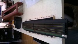
These drivers will be delivered to my next week:

not sure what i am looking at. looks like some folded membrane in between magnet rows. but there is hardly any room to move ? can you enlighten me how it works or do you have more pictures ? or a brand of some sort?
i do notice the smaller fold in the middle. probably for high frequency only, and is les wide and less deep to prevent phase issues and low roll off. but still i wonder how this apparatus works
same question here is has it forward movement or side ways like an AMT ?
Last edited:
Thx Jensen, well this is in fact sort of a AMT, although its not a perfect dipole(like an ESL or an amt comes close depending on the maagnet structure), since the back is considerable different to the front, at the front the airs gets squeezed by the 2 ribbons that move in opposite directions. but at the back it is the 2 ribbons than move towards or away from the magnet structure(so it has 2 cavity's compared to 1 bigger at the front). so if you would measure both sides they ought to be different. i like the fact they decreases dept of fould for the tweeters section since this a cullpit for high frequency's. another funny thing is that the ribbons are in the highest field possible close to the magnets. unlike normal ribbons in a big gap there is usually a weaker field in the middle compared to the edges of the ribbon. here they are almost at the strongest field possible. but when pushed it will get uneven. when at a loud positive peak the ribbon will find itself in a weaker field then a loud negative peak(closer to the magnet)
i wonder if this is patented.
i wonder if this is patented.
My hope is you will measure itPatent is pending. The tweetersection has it own circuit. A 2 way driver!
- Status
- This old topic is closed. If you want to reopen this topic, contact a moderator using the "Report Post" button.
- Home
- Loudspeakers
- Planars & Exotics
- Planar magnetic with central tweeter?