Hi,
just repaired a Pioneer M25, the failure was in the rail regulators.
On power up there was an initial offset of 0,5V on one channel that faded away after warm up.
Now one heatsink gets slightly warmer than the other.
There are 4 pots each channel and I do not know what to do with them...
Anybody have an idea or schematic please ?
hi,
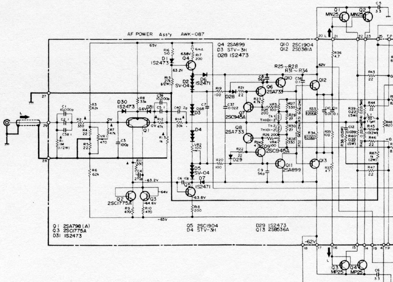
I had saw the M25 sch.IIRC,each channel of M25 has two pots which is 100 Ohms for adjust the protect current,and one pot for adjust the offset .....like the KRELL KSA100 sch.
If you research the KRELL KSA100 sch,and trace the M25...I think you can easily find the pot for adjust offset.
I had saw the M25 sch.IIRC,each channel of M25 has two pots which is 100 Ohms for adjust the protect current,and one pot for adjust the offset .....like the KRELL KSA100 sch.
If you research the KRELL KSA100 sch,and trace the M25...I think you can easily find the pot for adjust offset.
My scanner is worse....I just check my paper,the 4 pots is :
VR1(470 Ohms) for adjust offset
VR2(220 Ohms) for adjust the idle current of power stage
VR3 and VR4(all 100 Ohms)for adjust the limited current of pretect circuit.
I can't see your attachment.there are some M22 pictures which the brother of M25,M22 is class A,M25 is class AB.
good luck
X.G.
M22 pictures
http://amp8.com/sub/tr-amp/pioneer/pi-m22.htm
KSA100 schematic
http://www.diyaudio.com/forums/showthread.php?s=&threadid=12514&perpage=10&highlight=&pagenumber=2
Thanks,
VR1(470 Ohms) for adjust offset
VR2(220 Ohms) for adjust the idle current of power stage
VR3 and VR4(all 100 Ohms)for adjust the limited current of pretect circuit.
This is from M25 ?
M25 board looks different from M22.
Also it seems M22 does not use ringemitter transistors, 4 different output 2sa / 2sc devices...
What I have read is that M25 is class A up to 30W and B up to 120W.
yes,what I said is according to the M25 schBernhard said:Thanks,
VR1(470 Ohms) for adjust offset
VR2(220 Ohms) for adjust the idle current of power stage
VR3 and VR4(all 100 Ohms)for adjust the limited current of pretect circuit.
This is from M25 ?
")
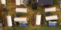
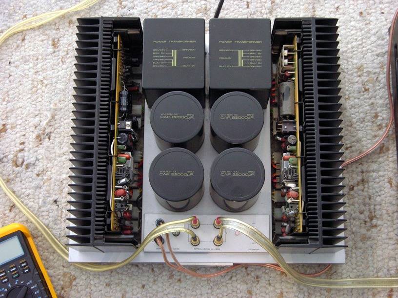
jacco vermeulen said:Left and right are identical.
Amps yes, pcbs no. Right channel has rectifiers, left channel has protection.
Not sure but I think it is like marked now in the picture.
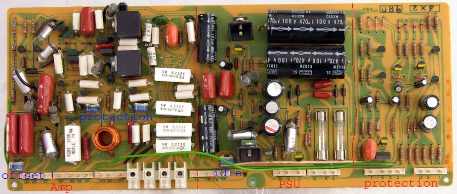
I meant the part of the amplifier section i reposted, these should be the current trimm pots.
Already saw on the top view of the M25 that left and right pcb's are not the same.
Division as you have drawn looks right:
for the amplifier section;
- dual-device with filter on the entrance,on the left.
- Vas and driver section in the top.
- output zobel network in the bottom section.
- 0.22Ohms/ 5W emitter resistors on the right part of the amp section.
Center part clearly is a dual rail voltage regulator for the front end ofthe amplifier.
jacco vermeulen said:I meant the part of the amplifier section i reposted, these should be the current trimm pots.
Idle current ? Why two ?
Or current limit / protection ?
I will replace all electrolytics for the amp's next 25 years...
the type of zener diode is WZ-320 which is 32V.Bernhard said:Ok, I will try.
As you have the schematic... There is a zener diode in the regulators, it was dead and I can not identify it. Can you see the type ? 30 V ? 33V ?
Thanks.
the output volt of regulator is +65V and -65V
BTW:I didn't see the original M22 sch,but I saw a M22 clone sch a few years ago....it is close to the M25 sch.
the thermistor thing ?
No, just checking my sanity.
The thermistors are part of the protection, depending on their hot value they'll reduce output current by a third, as from 10A to ~6.5A ideally. (quicky resistor value glance)
Why remove the feedback caps, they help to raise bandwidth ?
Why remove the feedback caps, they help to raise bandwidth ?
Are you shure ? It is 1 uF.
No cap is the best cap.
- Status
- This old topic is closed. If you want to reopen this topic, contact a moderator using the "Report Post" button.
- Home
- Amplifiers
- Solid State
- Pioneer M25 power amp bias & offset adjust ?