Searched web and found this thread.
oscillation in a preamp
This is what it looked like on my scope...which caps are my bypass capacitors? Should I check those?
oscillation in a preamp
This is what it looked like on my scope...which caps are my bypass capacitors? Should I check those?
Attachments

Just caught it. Was playing music on low and turned volume down to zero very fast and scope went blank as trace went off screen. I hear a small pop in speaker when it happens. Changed to 5V/div and here is what I saw. Again, it only lasted a few seconds. Took pic and it went away, back to 7mV.
Attachments
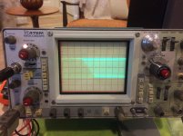
That certainly looks like instability/oscillation.
And just to be sure, you have the scope connected before the speaker relay so that you are seeing the output of the amplifier at all times, whether or not the relay is active.
Well bypass caps are any rail decoupling... bit of an unlikely suspect I would have thought.
What you really need to do is to see if you can provoke the problem by tapping and bending the board/s. That has to be the first step.
You could also couple the second trace of the scope to the power amplifier input to try and get an idea of whether the problem shows there as well.
Mooly, since getting the scope, I have only connected it to the speaker outputs, since I don't know where to go from there, and it is the most obvious symptom when things act up. And while I'm familiar with what each board is doing, I'm not sure where common term items are located. Bypass caps? Power Amplifier Input? So far I have not been able to provoke things, having poked, prodded, tapped here, there, nothing.
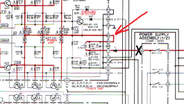
I can follow the schematic and board layouts, if you can tell me exactly where you suggest checking the power amp input. Are you referring to the Voltage Amplifier Assy board and the supply voltages (+59/-59V) that feed the MOSFETs?
I can follow the schematic and board layouts, if you can tell me exactly where you suggest checking the power amp input. Are you referring to the Voltage Amplifier Assy board and the supply voltages (+59/-59V) that feed the MOSFETs?
The scope goes anywhere on this line up to the point marked with a cross (which is where it enters the relay).
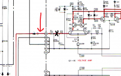
The input can be checked as shown but connect the scope to the side of the resistor shown, not the transistor side marked with a cross.
Both scope ground leads can clip to the metal chassis (make sure the clips are secure and can not flirt of and short anything out)
The input can be checked as shown but connect the scope to the side of the resistor shown, not the transistor side marked with a cross.
Both scope ground leads can clip to the metal chassis (make sure the clips are secure and can not flirt of and short anything out)
Attachments
OK, will do with the whacking. I've hooked Channel 1 probe to left speaker outs and Channel 2 probe to Left Output Assy, post 71 that leaves board and goes to protection relay. Both measure the same voltage (7.4mV) at idle. When ipod is playing, when I turn amp on, I see immediate results on post 71, and then after relay clicks I see results on speaker outs.
I put DMM on post 59 on Voltage Amp Assy (pic 2 you posted) and was reading 0V about 30 minutes ago.
I put DMM on post 59 on Voltage Amp Assy (pic 2 you posted) and was reading 0V about 30 minutes ago.
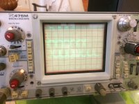
OK, more forceful tapping Voltage Amp Assy board in the area of the Left channel MOSFET got a reaction! Left speaker drops out. Tap some more and it starts playing again. Here is what I see on scope.
Looks like two traces, as probes are not matched even though they are on same settings (5V/div) as I have seen before.
I will try and pinpoint exact component leg and reflow it. If I can't I'll reflow things in this area.
Looks like two traces, as probes are not matched even though they are on same settings (5V/div) as I have seen before.
I will try and pinpoint exact component leg and reflow it. If I can't I'll reflow things in this area.
Attachments
This is classic fault-finding playing out in practice and I'll admit its not always easy to pin point the problem. Its worth looking for any parts that may not be pushed through the board as well. Look at post #15 here:
http://www.diyaudio.com/forums/digi...0-kss240-restoration-project.html#post3305236
Look for any bad crimping of wires in plugs and sockets as well.
http://www.diyaudio.com/forums/digi...0-kss240-restoration-project.html#post3305236
Look for any bad crimping of wires in plugs and sockets as well.
So Mooly, the area that I was able to get a reaction and saw the amp go into oscillation...how do I interpret what was happening there? A bad connection there led to oscillation, but I don't think it was tripping the speaker protection relay as the oscillation was always detectable at the speaker output. That being said, why did speaker just shut off? Shouldn't I have heard some sort of noise from the speaker? If relay did cut-off, would there have been anything measurable at the speaker outs?
Its difficult to say what was happening without knowing exactly which component/s etc had the intermittent connection. Depending what it was you might have to simulate the amp under those conditions to see what was going on. Its very easy to turn an amplifier into an oscillator inadvertently.
I don't know why the speaker shut off... and can we be 100% sure the relay wasn't tripping. You could perhaps look at the speaker output on the scope again with the relay tripped out and see what sort of hash/noise is present. The speakers leads will pick anything and everything up because with the relay 'open' they can not dump that hash into the low impedance output node of the amplifier.
I don't know why the speaker shut off... and can we be 100% sure the relay wasn't tripping. You could perhaps look at the speaker output on the scope again with the relay tripped out and see what sort of hash/noise is present. The speakers leads will pick anything and everything up because with the relay 'open' they can not dump that hash into the low impedance output node of the amplifier.
I guess to that point, if the relay was tripping, wouldn't that stop all current from reaching the speaker outputs to prevent damage to the speakers? And wouldn't that include the 800mV DC offset I was reading that was actually AC oscillation? As best I can tell, since I am able to measure the oscillation at the speaker outs, the relay either:
1) does not trip and the oscillation does go to the speaker, but the speaker drivers do not interpret that current/signal and the speaker falls silent;
2) it does trip, but the oscillating current filters through anyway, but again, the speaker drivers do not interpret that current and falls silent;
1) does not trip and the oscillation does go to the speaker, but the speaker drivers do not interpret that current/signal and the speaker falls silent;
2) it does trip, but the oscillating current filters through anyway, but again, the speaker drivers do not interpret that current and falls silent;
So I hooked the amp up to turntable and was still hearing less than desired quality of sound. This amp has a 3 way selector for cartridge selection. MC 3 ohm, MC 40 ohm and MM. all this time I have had it set to MM. But both my Grado blue and AT95e sound empty, especially when compared to a CD player hooked up. So I switched the phono selector to MC 40 ohm and what a difference. Sound is much fuller all around. Much better hi's and low's, especially at lower volumes.
Is it safe to run a MM cartridge on that MC setting? Should I be looking at phono stage as to why the MM setting sucks? Could it be just the pot/switch needs a good cleaning?
Is it safe to run a MM cartridge on that MC setting? Should I be looking at phono stage as to why the MM setting sucks? Could it be just the pot/switch needs a good cleaning?
An MC cartridge typically has a lot less output voltage than MM and also likes to work into a much lower impedance... which is what the 3 and 40 ohm settings are. Those two sound like transformer coupled inputs.
Yes its quite safe to use the MC setting but its surprising it sounds better for a MM. Wouldn't have thought there was any problem with the switching, at least nothing beyond anything obviously noticeable as you move them. You're probably liking the uneven response from using an MM into an MC input.
One possible solution is to look at the phono stage circuit and tweak the input and capacitance loading to suit your cartridge better. I'm no expert on that (not having owned a turntable ) but tweaking in that way is something that's commonly done.
Yes its quite safe to use the MC setting but its surprising it sounds better for a MM. Wouldn't have thought there was any problem with the switching, at least nothing beyond anything obviously noticeable as you move them. You're probably liking the uneven response from using an MM into an MC input.
One possible solution is to look at the phono stage circuit and tweak the input and capacitance loading to suit your cartridge better. I'm no expert on that (not having owned a turntable
) but tweaking in that way is something that's commonly done.- Status
- This old topic is closed. If you want to reopen this topic, contact a moderator using the "Report Post" button.
- Home
- Amplifiers
- Solid State
- Pioneer A88-x with Bad Channel