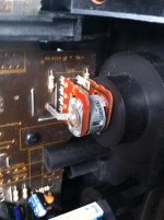
I recently got myself a lovely Pioneer A400 from Ebay but with a problem on the volume pot. The volume is stuck at minimum no matter how much you turn the pot. This is strange as I usually do get some variation/crackle/noise when I turn the pot.
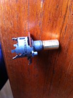
Anyway had a look inside and it appears to be an Alps with a 100KBX2 marking on it i.e. dual 100K linear. It has a split-shaft performing balance duty - this functionality will have to go unfortunately as I can't find anything like that to buy.
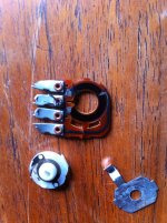
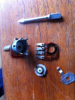
It also appears to have a forth pin as a 40% (or 60%) loudness tap. Since it was all mangled up I decided to get inside that pot - the destructive way - and share a few pics which maybe can help others.
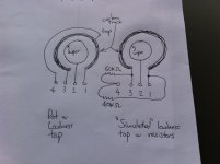
The pin arrangement looking at pins from the front of the pot, from left to right is:
1-CCW
2-Wiper
3-CW
4-Loudness tap
I also noticed there are a couple of ceramic caps where the loudness circuitry is. Maybe these can be replaced with audio bipolars or wima's as an improvement, can't imagine ceramics from the 80's sounding that good. Will look into that later.
I have found something that resembles that on Ebay so now I am waiting for it to arrive to continue with the repair. If everything goes well next step will be a recap.
Cheers
Anyway had a look inside and it appears to be an Alps with a 100KBX2 marking on it i.e. dual 100K linear. It has a split-shaft performing balance duty - this functionality will have to go unfortunately as I can't find anything like that to buy.
It also appears to have a forth pin as a 40% (or 60%) loudness tap. Since it was all mangled up I decided to get inside that pot - the destructive way - and share a few pics which maybe can help others.
The pin arrangement looking at pins from the front of the pot, from left to right is:
1-CCW
2-Wiper
3-CW
4-Loudness tap
I also noticed there are a couple of ceramic caps where the loudness circuitry is. Maybe these can be replaced with audio bipolars or wima's as an improvement, can't imagine ceramics from the 80's sounding that good. Will look into that later.
I have found something that resembles that on Ebay so now I am waiting for it to arrive to continue with the repair. If everything goes well next step will be a recap.
Cheers
Attachments
Last edited:
I also noticed there are a couple of ceramic caps where the loudness circuitry is. Maybe these can be replaced with audio bipolars or wima's as an improvement, can't imagine ceramics from the 80's sounding that good. Will look into that later.
Hi chatziva
I think you will find dipped polyester caps in most Jap vintage gear, not the worst nor the best.
look forward to you volume control replacement. good luck on the recap, take it slow and mod one section at a time.
it does the loudness EQ when the volume is turned below the tap, so yes no button.I was not aware the A-400 had a loudness button so why does it need a loudness tap?
it does the loudness EQ when the volume is turned below the tap, so yes no button.
I sure hope that is bypassable.
 Or is this perhaps the the secret to its gaining glory?
I sure hope that is bypassable.
nope it's automatic, no more forgetting to turn off the switch when the party gets started
saves speakers toomaybe its a vintage thing, as the speakers were different back in the day ~More eff. less excursion
Last edited:
I was not aware the A-400 had a loudness button so why does it need a loudness tap?
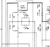
As others have mentioned the taps are permanently connected. If you look closely at the picture you attached you will see the point where resistors R731/732 are connected to the pot, they are the loudness taps. You can see them as little white arrows in the pics I have attached. The schematic would imply tapped at 40% however this is not the best service manual ever produced (the SA era service manuals where masterpieces!).
C733/734 are the ceramic caps I was talking about, they are not dipped polyester, they are indeed ceramic...yikes! They are hidden underneath the pot. I am thinking of using something like wima's to replace them, maybe under the pcb due to space.
Last edited:
Hi chatziva
I think you will find dipped polyester caps in most Jap vintage gear, not the worst nor the best.
look forward to you volume control replacement. good luck on the recap, take it slow and mod one section at a time.
Hi infinia
Nice to see you! Thanks will keep you posted. Yeah I guess dipped polyester is not that bad, but these are ceramic in the loudness circuitry. I have never seen ceramic in the signal path (well kind of) before!
Cheers
Last edited:
I sure hope that is bypassable.
The purist in me agrees with you that I should not like loudness circuits, however all the amps I had with loudness I am ashamed to say I almost always listen to them with loudness on. It's music salt is what it is!
Several people on eBay part out parts for old stuff. I see vol pots all the time. Do a search and you will one. Might not PC mount but something you can use. Pots go for about $25.00 or so
Thanks yes already ordered something from Ebay we'll see how it goes. It's very difficult to find loudness tapped linear pots these days!
Okay question for the experts...
I have been thinking... given the difficulties finding the right pot with loudness taps these days, would it be possible to ...emulate loudness taps by means of resistors soldered on the CW & CCW legs of a normal 3 pin pot?
See attached sketch to see what I mean. The pots are 100K in both cases.
I guess another option for the emulated pot could be a 100K pot with 30K & 20K resistors (more loudness effect) or even 120K & 80K resistors (less loudness effect)?
Would it work?
Attachments
Last edited:
Yes post 2 is an extract from the service manual.
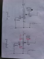
This is what I am proposing in red. Basically I am talking about introducing 2 shunt resistors 40k & 60k soldered on the CW & CCW legs and keeping everything else the same.
But what you are suggesting is simpler, a single shunt resistor soldered on the wiper leg. Hmmm interesting. What value though?
Attachments
Last edited:
Had a brainwave...
If we don't know what values to use, then let's use shunt trimmers...!
Either a shunt trimmer configured as a variable resistor (2 way mode) soldered to wiper, or trimmer in 3 way mode soldered to CW & CCW...
Values can be adjusted to taste then replaced with fixed resistors...!
100K trimmer should be a good starting point.
100K dual audio taper
or 220K dual LINEAR with shunt on wiper ~47K see here ESP - A Better Volume Control
better tracking on linear pots
> The other advantage of the 'fake' log pot is that linear pots usually have better tracking (and power handling) than commercially available 'log' pots, so there will be less variation in the signal between left and right channels. This is improved even further by the added resistor, which will allow a cheap carbon pot to equal a good quality conductive plastic component (at least for accuracy - I shall not enter the sound quality debate here).
the hardest part is finding a mechanical fit with hopefully dual shafts.
Last edited:
Ok thanks but bear with me I am trying to understand what you are saying.
For your first option you are saying that I should leave the loudness circuitry unconnected? Also wouldn't a log pot connected to fake log circuitry have an undesirable double whammy log effect? i.e. log(log(x))?
I like the second option but why have you gone for a 220K pot? i.e. double the original OEM part value? and not say 100K pot + 24K shunt?
Sorry for the questions, just trying to understand your logic.
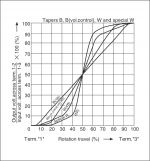
I don't know if its a linear law, alps uses the "B" suffix for both linear and audio taper (Vol control in the attached pdf) if you follow the "loudness tap" you will see that its grounded so its just changing the law below the tap (law faking.
So maybe Pioneer needing a dual concentric pot just faked it for the 1st 20% as thats where it matters the most?
Any way I'd replace it with something like this Alpha-Pot-9mm-100k-dual-concentric as it log you don't need the tap to fake it; not sure if the knobs would fit though?
As to those ceramics the schematic makes it look like they are shorted across the ground, maybe the are tying two ground points to shunt RF, I would only change them to ceramic NPO/COG or silver mica if thats the case...
regards
james
Attachments
tvi you're spot on!
Pioneer is using this tap as a fake law tap, not as a loudness tap...!! Damn I wasn't looking hard enough!!
Another good spot on the caps they are indeed shunted to earth. Again wasn't looking hard enough!! That's a bit unusual arrangement isn't though? What good is the cap if it's shunted to earth?
I like the alpha concentric pot. It looks like it'll work as an OEM replacement. Will do some measurements on the original pot.
Last edited:
- Status
- This old topic is closed. If you want to reopen this topic, contact a moderator using the "Report Post" button.
- Home
- Amplifiers
- Solid State
- Pioneer A400 Volume Pot Replacement