If anyone is still interested in the November 2006 AudioXPress article on DML, I have that issue. Here it is...
https://docs.google.com/viewer?a=v&...mYtZjdkZS00ZTY1LTgyOTQtNDc5NjZmMGE4NWQx&hl=en
https://docs.google.com/viewer?a=v&...mYtZjdkZS00ZTY1LTgyOTQtNDc5NjZmMGE4NWQx&hl=en
Nice article, is there anyway to print it out?
To the upper left of webpage under the "Google docs" logo click on "file". You can download the PDF and then print it.
I tried that foam poster board + PE exciters combo a few years ago. It was the worst thing I ever heard in my life.
Last edited:
NXT panel
Okay this is my very first post. Last year I got interested in building my own speakers for a home theater application needing extreme wife approval. Finally thought these NXT speakers might work as I would use a large rectangular panel with a painting on it ~ 1' x4'. So I bought 4 of the Dayton high shove transducers. I haven't found gator board yet but did try foam board from WalMart. It does make sound but it is very muted. Sounds like there are speaker behind a sound screen panel. I've just been trying various things around the house for now and not being overly impressed. It seems like people are either settling for gator board or honeycomb panel. I've got to figure out where to buy that stuff. I also didn't want to spend to much more as I already have $120 invested in the exciters.
I am not an audiophile by any means but I would like sound better than what is currently coming from the TV.
BTW are these shielded enough to go next to a TV?
I have a second home theater with Atlantic Technology speakers so the wife did not want a bunch of speakers or home theater in the living room.
I haven't found gator board yet but did try foam board from WalMart. It does make sound but it is very muted.
That's pretty much what foam board sounds like. Even the top of a pizza box sounds better.
How did you attach the exciter to the board (the tape I assume)? It needs to be a fairly rigid bond, like either mechanical or a hard glue with low damping properties to get the best highs.
I never tried Gator Board so I can't say how much better it is than foam board.
http://www.amazon.com/s/ref=nb_sb_noss?url=search-alias=garden&field-keywords=gator+board+3/16
Richeson Unison Pastel Gator Board - JerrysArtarama.com
I had attached the back of the exciter to a poplar board using double stick tape so I could remove it. I did not want to permanently bond the exciter to the foam board so I just held it in place with a pencil point pressing on the panel. Set up two for a stereo effect. I used two exciters per panel
Not sure if this is the right thread to ask... Has anyone played with these: WowWee? :: Amplifiers
It's a toy amp/speaker that uses an NXT type transducer.
I saw them on sale and got a couple for kicks. I removed the battery powered amp and wired the transducer straight to my amp. They sound pretty good to my ear. If anything, they seem to be weak on the low end. Unfortunately, I don't have the skill or equipment to do proper measurements on these. Has anyone else done so?
Hello,
Any NXT/DML panel builder out there?
Here is my recent experiment:

Any NXT/DML panel builder out there?
Here is my recent experiment:
An externally hosted image should be here but it was not working when we last tested it.
An externally hosted image should be here but it was not working when we last tested it.
An externally hosted image should be here but it was not working when we last tested it.
An externally hosted image should be here but it was not working when we last tested it.
Hi,
Thanks for your interest.
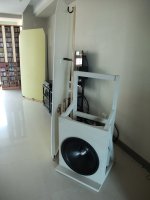
Here's how I set them up (for now):
The amp driving the panels is unusual with a 20 Ohm output impedance. It's setup by a mixed voltage and current feedback method brought up by Mr. Rod Elliott here: Variable Amplifier Impedance
All 5 excitors wired in series with 4 of them bypassed by a cap. Because of the bypass cap, the group of 4 is unseen (shorted) in the higher frequency range, thus a clear trend of high impedance in the bass and low impedance in the mid and high frequencies. (plateau under 200Hz, broad valley center around 2.5kHz)
The high impedance drive interacts closely with load impedance, thus an output curve almost tracking the impedance curve:
That's by calcuation. In reality, it seems the boost in LF is not so much. And I need addtional EQ to make it flat down to 40Hz or so.
Later I tried active xover with an amp driving the single unit in fullrange, and another amp driving the 4-unit group. So I got freer adjustment and more boost actively. However I didn't like the sound of active version (for the first time). It's not so coherent as passive version.
At its best (after EQ, of course), I got about 40Hz ~ 20kHz bandwidth with proper tonal balance. And they can play quite loud. No numbers. Loud enough to be painful or bother the neighbors.
But when it plays loud, beyond a certain point, it starts to sound compressed and thickened. I'm not sure where exactly the problems come from. Maybe it's the limit of excitors, or the undamped panel itself, or the improper securing means, maybe all of them...
Thanks for your interest.
Here's how I set them up (for now):
The amp driving the panels is unusual with a 20 Ohm output impedance. It's setup by a mixed voltage and current feedback method brought up by Mr. Rod Elliott here: Variable Amplifier Impedance
All 5 excitors wired in series with 4 of them bypassed by a cap. Because of the bypass cap, the group of 4 is unseen (shorted) in the higher frequency range, thus a clear trend of high impedance in the bass and low impedance in the mid and high frequencies. (plateau under 200Hz, broad valley center around 2.5kHz)
The high impedance drive interacts closely with load impedance, thus an output curve almost tracking the impedance curve:
An externally hosted image should be here but it was not working when we last tested it.
That's by calcuation. In reality, it seems the boost in LF is not so much. And I need addtional EQ to make it flat down to 40Hz or so.
Later I tried active xover with an amp driving the single unit in fullrange, and another amp driving the 4-unit group. So I got freer adjustment and more boost actively. However I didn't like the sound of active version (for the first time). It's not so coherent as passive version.
At its best (after EQ, of course), I got about 40Hz ~ 20kHz bandwidth with proper tonal balance. And they can play quite loud. No numbers. Loud enough to be painful or bother the neighbors.
But when it plays loud, beyond a certain point, it starts to sound compressed and thickened. I'm not sure where exactly the problems come from. Maybe it's the limit of excitors, or the undamped panel itself, or the improper securing means, maybe all of them...
I didn't mention that there're several intrinsic resonant peaks on the panel itself (or maybe also related to the positions of the excitors). Now they are at 6.3kH, 2.5kHz, and/or some others not so pronounced around several hundreds...
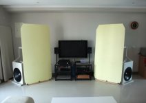
Along the experiements, I think I'd better release the LF load on the flimsy panels (and poor little drivers). So I added cone woofers for bass augmentation - my old 18" pro woofer on OB.
I kept the panel running fullrange, but not anymore in the stress of additional LF boost. The OB (dipole) cone woofers are arranged so that they cancel a portion of LF produced by the panel at the rear side (negative lobe of the dipole bass meets bipole NXT panel). Two major goals for this: less LF trapped between panels and wall, and keeping the bass sounds appear at far left and far right. (refer to the "OSD" concept...)
Attachments
Last edited:
Hello everyone, I'm new to the forum...
I have successfully constructed a set of planar panels from Sitka Spruce soundboards I have constructed based on piano soundboard construction theory (namely Del Fandrich's soundboard acoustics book). They measure approximately 4' x 6', yet are organic in shape (no parallel or straight edges except the bottom). Grain has been run at 60degrees relative to the X axis and ribbing has been added to the rear with an ark diameter of 60 feet. The board is mated to a heavy outer frame (bottom is free of frame), much like an acoustic piano stood on end. Thickness of the soundboard is just less than 3/8 of an inch and has been tapered (1 foot from the edge) to 1/4 inch along 1 side, allowing for increased low end output.
-The higher frequencies transmit well through the thicker board, but efficiency and low frequency response are compromised.
The properties of Sitka Spruce are very elastic and light, allowing for great efficiency. The tonal characteristics of this wood are remarkable, not surprising, as it has been the material of choice for 100's of years when constructing high end pianos, violins, cellos, etc.
Each side is driven by a Clark Synthesis TST 329 Tactile Transducer (largest model to be horizontally mounted) that is attached to a Maple "bridge" (approx 1" x 1") that runs diagonally across the soundboard. This has given a much smoother response than my previous single-point-source mounting position. I adopted this from piano design theory where vibration is dissipated to a larger area of the soundboard and not as subject to panel resonant nodes present in a single-point-source contact point.
The low frequency response is phenomenal, yet crossed over (48db/octave) at 70 Hz where a large pair of transmission lines take over.
I have experimented with a number of materials and drive configurations of planar panels over the years, and nothing has come close to the Sika Spruce. Highly recommended.
If you guys would like to experiment with a spruce soundboard, may I suggest you look for an old piano (preferably one written off) and use the soundboard from that. The challenge comes when finding an identical pair (hence why I constructed them). But it will give you an idea of the acoustic characteristics before constructing these. There are some piano technicians that can build soundboards for you as well (not cheap tho). And if you do find a used one that has been repaired, don't get too scared, as it's not always a bad thing. If the piano is quiet when played - the soundboard is done.
When I get back in town, I will attempt to provide pictures (as the wood is quite beautiful).
PS. I'm in love with this forum - you guys are dedicated, passionate, and a fantastic resource. I look forward to learning from all of you!
Cheers.
...
I'm not sure where exactly the problems come from. Maybe it's the limit of excitors, or the undamped panel itself, or the improper securing means, maybe all of them...
The frame holding the exciters seems not to be very
rigid, a good frame for the motor would be helpful IMO.
I feel you may have accounted for the coincidence
frequency of the panel by letting the impedance fall
above 2Khz, which seems a valid approach with your
"close to current drive" amplifier. This way you
compensate for the rising efficiency of the panel around
and above coincidence frequency i guess.
In the 'hundrets' of course it is very likely, that the
panel's behaviour is not balanced, because modal density
is not very high at LF.
Since your "group of 4" is rather concentrated, they all
'see' nearly the same mechanical load due to the panels
modes: They see the same "driving point impedance".
Using a more distributed configuration, there is an
opportunity to average the mechanical impedance over
more driving points.
Since you have means to visualize the driving point impedance ...
Please note that local driving point impedance changes, if
you alter the 'hinges' of the panel.
Kind Regards
Last edited:
Hi LineArray,
Thanks for your suggestions
The pictures couldn't tell all the stories. Let me explain. The thin sticks are supposed to support the mass of excitors without interfering their fore-aft movements. I hope they would act like upside down pendulums. Prior to the fixing of panel, I installed these stick/excitor assemblies first. Without panel, the one with sigle excitor has a self-resonace of 2~3Hz; well under 1Hz for the 4-unit group. I guess these are far enough from any audible resonances of the panel
In my first two experiements, excitors were self-supported by their own VC formers and plastic feet -- as the securing method of original design. OTOH, in some other commercial product or in other panel builders' works, there're 'spines' for supporting the excitor (like you've mentioned). Between them, I'm not sure which is better.
I just imagine the excitor should be 'riding' on the (chaotic) waves, giving only the initial 'excitment' and then let the panel do the rest. With free floating support, the mass of excitor would interfere less with the vibrations of panel. At least we may avoid another set of mass-spring sub-system (as much as possible).
Of course it's very likely that my idea can't be thoroughly realized. It's just a trial. More will come.
And the concentrated 4-unit group was for simplification. Those two fixing spots on panel are both at 1/3 positions which is suggested by a member of another forum. Again, more trials will be needed. I'd need some other way to secure the excitors, as my flimsy foam boards were already damaged on the rear side. It's too fragile for repeated experiments. And I haven't figured out a proper and effective way to support several excitors and maintain their free floating actions...
More will come, for sure.
Hi LineArray,
Thanks for your suggestions
The pictures couldn't tell all the stories. Let me explain. The thin sticks are supposed to support the mass of excitors without interfering their fore-aft movements. I hope they would act like upside down pendulums. Prior to the fixing of panel, I installed these stick/excitor assemblies first. Without panel, the one with sigle excitor has a self-resonace of 2~3Hz; well under 1Hz for the 4-unit group. I guess these are far enough from any audible resonances of the panel
...
A valid approach in my view, nevertheless your
"standing pendulum" will have higher order
"bar modes". But the approach is creative, higher
order modes could be tackled by damping.
...
I just imagine the excitor should be 'riding' on the (chaotic) waves, giving only the initial 'excitment' and then let the panel do the rest. With free floating support, the mass of excitor would interfere less with the vibrations of panel. At least we may avoid another set of mass-spring sub-system (as much as possible).
...
That 'riding on the chaos' is a very aesthetic picture,
but since the resonance of your 'pendulums' will
be subsonic the movement of the motor will be mass
hampered in the audible range.
The panel is acting upon the spring predominantly,
which is given by the VC suspension of the exciter.
Of course you may circumvent problems in adjusting
the VC rest position, as your pendulum is kind of
'self adjusting' - on the other hand you will need a
"transport lock" for the exciters, when moving your
speakers to the next audio show ...
Please move on and good luck ...
- Status
- This old topic is closed. If you want to reopen this topic, contact a moderator using the "Report Post" button.
- Home
- Loudspeakers
- Planars & Exotics
- PIEZO NXT type panel