Thank you again mjf!I have now included you in my prayers.he...he..(you don't know, how much I appreciate this)
I am able to get both these types easily from a company called https://www.elfa.se They have many branches around europe. A bit pricy though!
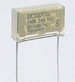
With regard to PMR 209, it is an anti surge cap, & reading from the data sheet it has a very low resistor in series with it. I assume it is therefore an X type cap? (Pl.let me know if you need the data...can mail it to you)
So, does it matter which way I connect these?
Supply +/- C, + R to ground or the other way around? I hope I got the question right.!
Thanks again.
I am able to get both these types easily from a company called https://www.elfa.se They have many branches around europe. A bit pricy though!
With regard to PMR 209, it is an anti surge cap, & reading from the data sheet it has a very low resistor in series with it. I assume it is therefore an X type cap? (Pl.let me know if you need the data...can mail it to you)
So, does it matter which way I connect these?
Supply +/- C, + R to ground or the other way around? I hope I got the question right.!
Thanks again.
Attachments
hello.
now i have found the rifa 209 cap.these are the r-c units against arcing and sparking, for contact protection (should increase the life of contacts),e.g. relays,thyristors and the contacts of your on-off switch of your power supply.usually this unit (a res in series with a x - cap) is connected to the contacts of the switch (but sometimes they are connected to the load...........depends on the application).
i think it does not matter in which way you connect them to the rails or contacts..........it is a simple r-c network.
can not tell much,because i do not use them.............
thank you for the email.............would you like to show a foto here?
greetings..........
Hi mjf,
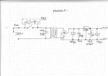
Thanks for the diagram,It makes things clearer to me now.
We have 220v ac ie;110v ac on both lines here (star config?) + earth.
hence don't have a neutral line at all.
So can I use PMR209 across these live lines across the primary side of the trafo do you think? I need to use something as a mains suppressor. A thyristor perhaps?
I suppose ESR caps for the 1000uF's won't do any harm either?
PME271 is ok in the secondary side.
Ok...here's the 9 month old baby under wraps with strict orders from the Dr. Due to arrive any time soon.....but can be a bit of a "crybaby" sometimes.so been making a nice little "Cot"...i mean a metal case at the moment.
Sorry,won't allow anything larger than this file format!!
Attachments
hello.
sorry i am no "mains expert"................norway power plants???
please do not connect the x-rated suppressor caps from mains to earth (the value is to big and you need y-rated caps -with only a few nf,e.g. 1nf ......4,7nf).
mostly i use pme caps connected to the primary mains.
yes,the 1000uf elcos should be low esr types like panasonic fc or so for better performance............
greetings..................
Hi mjf,
I've now decided to use this circuit (please see attachment) instead of the earlier one shown.I've also started a new thread "Small Power Regulated Power Supply" under "Power supply" as to not to deviate too much from my original posting on PIEZO DISC PREAMP"
So looking forward to your continued help & advice in the new post.
Attachments
hello.
if you want to use a 2x12volt transformer you can reduce the output voltage of the regulators a little bit (to 13v or 12v or so),because the standard opamps work at lower supply voltages without problems .
and you can substitute the adjust res by a trim pot(e.g. 1k) and a res(500 ohm or so) in series.
if you use a bridge rectifier in place of the four diodes the number of parts will be reduced and it is easier to build.......
greetings...........
Yes,good thinking! why didn't i think of this before?
As I've mentioned earlier, am actually running all my circuits on 2x 9v Lithium battaries at present. Although they work quite well, i just wanted to see how much (more) headroom/dynamic range I can get by using a dual 15v supply & see if there would be any vast improvement in noise levels as well.
So I will first measure how much the the caps are outputting & then can adjust the regulaters accordingly as you've suggested.
Originally posted by teleman
So I will first measure how much the the caps are outputting & then can adjust the regulaters accordingly as you've suggested.
heatsinks...............have a look at the temperature of the regulators.
perhaps you will test it with different loads (resistors).......the standard opamps need only a few ma.
greeting.................
Hi... I'm into using piezo discs for "mics" for underwater purposes. and the charge coupled preamp looks quite inteeresting- but I have another question:
Which size of discs seems most useful for mic purposes?
The larger discs have lower resonant frequencies, at least used as an output transducer, but generally also larger capacitance.
One could assume that a larger disc also would be more sensitive for mic purposes, but maybe not?
Experience or opinions are much appreciated......anyone?
Exactly. I'm servicing some equipment built by someone else, and quite frankly I don't like the underwater design very much - the disc is encapsulated in a very large blob of semi-hard silicon mounted on the outside of the hull.
I'm seriously concidering making my own design, but I'm wondering about which type of disc might be the better choice.....
-otherwise, I've been working in EE for over 30 years, so that's not my problem. I just haven't used these piezo discs as a mic elements before.....and quite frankly, there isn't much info to find either
phase_accurate said:There was such an underwater mic thingie using a piezo disc in elektor recently.
Regards
Charles
Would you care to specify which one......??
")
We subscribe to Elektor at work, but I mostly just go through them very quickly, as I often find them full of strange stuff I don't care about........this one obviously skipped my attention!
Then some of the copies get scattered around, depending on who's taking interest in something......
IIRC it was during winter 08/09 but I don't own it personally - I just read through it at a newspaper agent.
A workmate once had a paperback on underwater electronics for divers. There they used thicker piezo elements but these had very narrow usable frequency ranges. They encapsulated them into flexible compartments that were filled with some cooking oil that has about the same sound propagation as water.
Regards
Charles
mjf,
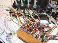
sorry,I forgot to reply to your earlier post.I have salvaged a nice piece of heatsink from an old pc PSU,sawed it in two & now have 2 solid heatsinks for the regulators,fitted to 3mm aluminium plates.
btw,I'm using 317T/337T's since i had a couple in my "stash"!
got a few more good circuit ideas from the the 317/337 data/application sheets as well.
AurorB,
Here are 3 links that might help you in your search .......
http://www.airmar.com/pdfs/technical/sensor.pdf This one has a circuit as well.
http://www.piclist.com/techref/io/sensor/sonar.htm
http://www.morganelectroceramics.com
Here are 3 links that might help you in your search .......
http://www.airmar.com/pdfs/technical/sensor.pdf This one has a circuit as well.
http://www.piclist.com/techref/io/sensor/sonar.htm
http://www.morganelectroceramics.com
teleman;1876461 We have 220v ac ie;110v ac on both lines here (star config?) + earth. hence don't have a neutral line at all. [/QUOTE said:ARE YOU SURE?!?!?
I doubt that very much indeed. star config would require 3 lives and one neutral!!!
Just like the UK you have 220V*root3 = 220*1.732 = 380V in 3 phase from a substation, one phase and the neutral is split off. This is what supplies your home with single phase AC.
(we have around 440V but the same system is used throughout the world, with different single phase voltages)
nice project though...i have a old donor electric guitar i have thought about trying this piezo trick with a number of times. No i may have the impotus to actually get around to it!!!
Last edited:
Teleman is mostly right..
most of the norwegian consumer networks are 230v delta, that is 2 hot wires and ground - no neutral.
FWIW - i think it's only Norway and Peru who have kept the IT network configuration, although for some years now, new consumer areas ( complete new networks with substationand grid) are now built as 400V star, neutral and all....
- Status
- This old topic is closed. If you want to reopen this topic, contact a moderator using the "Report Post" button.
- Home
- Live Sound
- Instruments and Amps
- Piezo Disc Preamp