and the power supplies were $8 each delivered off fleabay
Yep, one of the advantages of the pc-age is that surplus smps costs zip.
Don't those type switchers run in the 40+KHz region?
I believe this one runs 100K and I have not yet been able to pickup any high f's using my ears
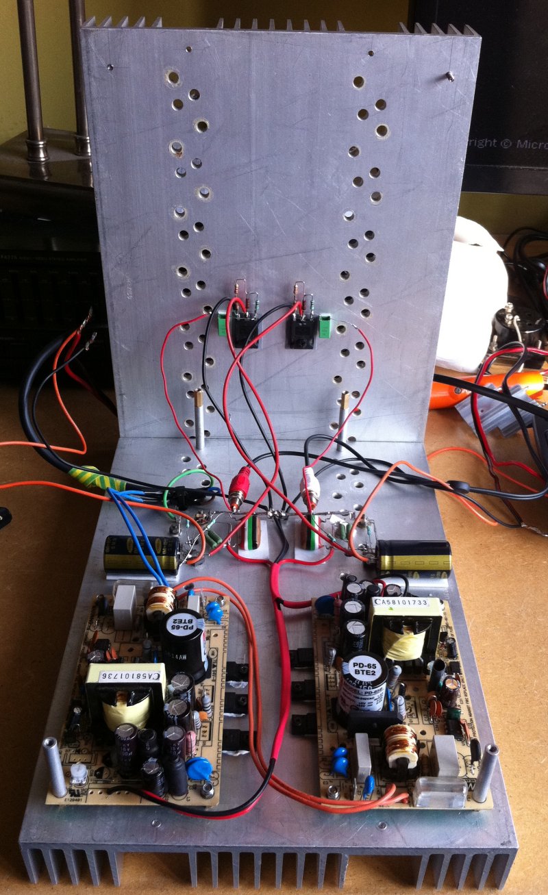
 . I do plan on encapsulating the psu to keep rfi low and safeguard myself from flying parts might things go south
 I'm running a miniA in my garage off a pair of 12V 6A switchers (apex jr for $8/pc) but I threw in a tiny RC filter afterward. I felt that a 1000uF cap cleaned it up a lot.
I've added a small 1uF which together with the smps choke seems sufficient to kill any remaining ripple. I'll dig up my oldskool scope to see if there's any truth in what I'm saying.
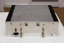
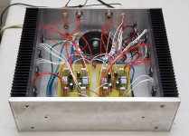
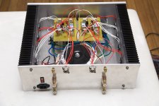
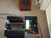
As promised some more pics, as you can see I cleaned things up a little and decided to bring the smps switch fet also to the heatsink. Kind of a tricky decision because I had to extend the fet wires which could cause havoc but sofar all looks stable.
I remember myself studying the back of a Philips tv when I was around 8 in age, wondering what these colourful candy shaped thingies were for. Ahh, those were the days. AC125, AD149, AA119, uA741. Time flies.
Nelson Pass xmas trees
bucket switcher anyone ?
Having listened to this thing for some time now I find the output to be pretty enjoyable although a bit skinny, according to my scope it's limited to about 16V top-top which isn't much when driving english speakers. I hesitate to up the voltage since things are already getting pretty hot and dislike the idea of burning more money. I feel the next step should be to replace the current source with a buck switcher which should half the dissipation. Like being done here. Should be pure eye candy to build this thing right under a pentium cooler ......
Having listened to this thing for some time now I find the output to be pretty enjoyable although a bit skinny, according to my scope it's limited to about 16V top-top which isn't much when driving english speakers. I hesitate to up the voltage since things are already getting pretty hot and dislike the idea of burning more money. I feel the next step should be to replace the current source with a buck switcher which should half the dissipation. Like being done here. Should be pure eye candy to build this thing right under a pentium cooler ......
Last edited:
Cascoded - Balanced XF5 for ~$600 with the finest quality parts
I posted this build in my F5 thread, but I'm sure this thread has different followers. The photos are of my Cascoded Balanced XF5.
I used:
I'm putting together a "How To" on the build, including the PCB layouts. I'll post it when I get it all together. If you're interested, let me know.
I intend to clean up the wiring when I have a chance, and change the toroid to the front of the case, from the back. I'm in process on two more F5 variations, hopefully they turn out as well.
I posted this build in my F5 thread, but I'm sure this thread has different followers. The photos are of my Cascoded Balanced XF5.
I used:
- 12v - 800VA Antek toroid (capable of 1000VA)
- Matched Toshiba 2SK1530/2SJ201 outputs - 4 pairs from ZhouFang
- Matched JFETs (2SK170BL and 2SJ74BL - with differential match for degeneration)
- Two Conrad MF35-151.5 Heat Sinks
- Custom case with 1/2 inch Aluminum faceplate, balanced and RCA inputs
- Fukushima resistors
- 8*MSRF1560 Ultrasoft diodes
- Custom PCBs
- Power Supply - CRC (in the style of the F5 Power Supply). Currently 8x18000uF, will be 4x 68000uF when I upgrade the case
I'm putting together a "How To" on the build, including the PCB layouts. I'll post it when I get it all together. If you're interested, let me know.
I intend to clean up the wiring when I have a chance, and change the toroid to the front of the case, from the back. I'm in process on two more F5 variations, hopefully they turn out as well.
Attachments
Last edited:
I'd use relatively thick ceramic pads to isolate the switchers from the heatsink.
Both schottky's and mosfet are of the fully insulated types, i.e. the backplate is covered in plastic and allows mounting without the regular mica wafer. While at the subject, could you tell me what the thinking is behind those ceramic pads ? What's their advantage over standard isolation wafers ?
Lots of fearless amp builders today.
Hi Nelson, thanks for comment #666
 would you like to comment on the use of a switched current source to half dissipation ?
Last edited:
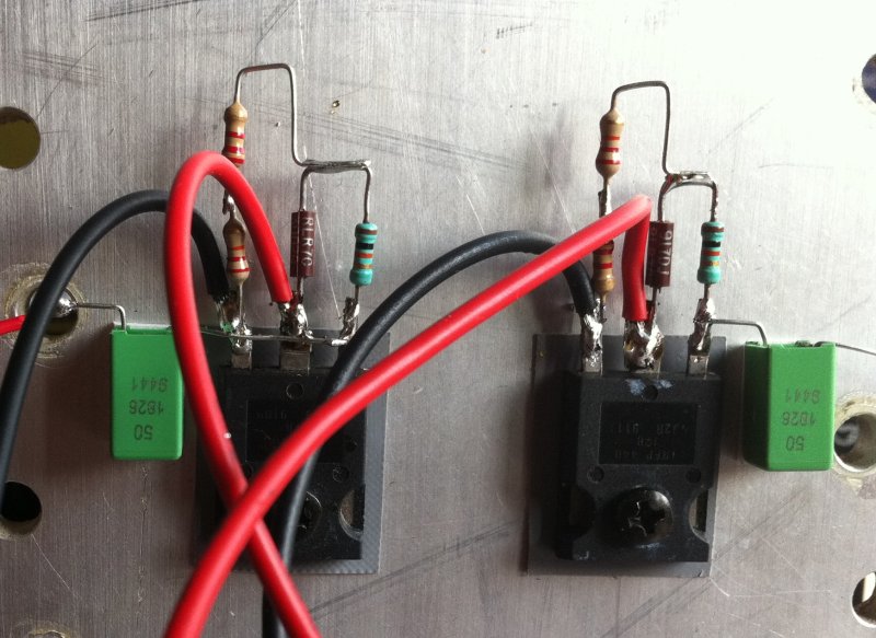
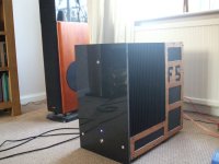
I also happened to have a pair of irfp 440's laying around which got desoldered out of an old AS/400 psu,
Just thought I'd add that I spent 18 months building these in the late 90s (IBM@Rochester) before I wised up and went to school. I remember slotting 100 x 20GB drives in some of these.
... actually I "graduated" from build, and then spent 6 months in hardware support explaining to people how to start their server after power failure... THEN I wised up.
Lots of fearless amp builders today.
Speaking only for myself - I couldn't have done it without you, in more ways than the obvious.
Thank you for your interest and guidance to me, and the forum.
Thank you for your interest and guidance to me, and the forum.
Yes, nelson is da man.
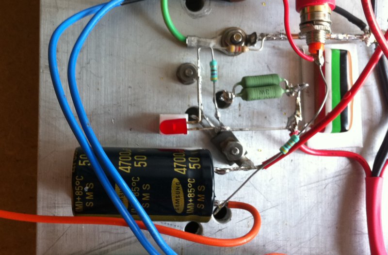
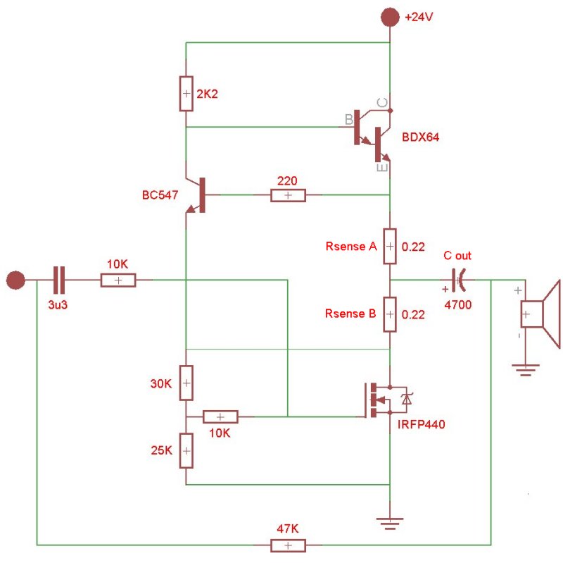
Hereby my schematic sofar, should look pretty familiar except maybe for the current sensing resistor setup which I picked up from the pass d thread. As far as I understand it allows for the load (from bdx into 4700 cap) and unload (from buffer cap into IRFP) currents to be separated from each other, a bit like push-pull magic.
Both schottky's and mosfet are of the fully insulated types, i.e. the backplate is covered in plastic and allows mounting without the regular mica wafer. While at the subject, could you tell me what the thinking is behind those ceramic pads ? What's their advantage over standard isolation wafers ?
I only mentioned ceramic because that's what I use (not your regular stuff but a ceramic-based 2mm thick material I get from a friend).
In general, and based on my experience with switching amplifiers, it's recommended (and I'm quoting from Tripath's Application Notes 17 - "DO’S AND DON’TS WHEN DESIGNING FOR EMI COMPLIANCE"):
...where external MOSFETs are required, use low dielectric constant insulators to prevent the switching noise from coupling onto the heat sink. Aluminum Oxide insulators or polyester film thermally conductive insulators (such as Poly-Pad K-10 from The Bergquist Company at Thermal Interface Material, Thermal Management ~ The Bergquist Company) can be used with the MOSFETs. Both of these insulators reduce radiated EMI from the chassis.
Moreover, quoting from Tripath's AN11 ("DESIGNING FOR EMI REGULATORY COMPLIANCE"):
The use of thicker insulators under the output FETs has been shown to be very effective at broadband suppression.
Hope that helps.
Last edited:
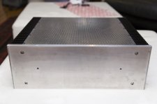
NY - very nice DIY case - i like those immersed bolts!
Thanks for the props, but I didn't build the case - I don't have any real tools (I finally bought a drill press of PCBs and a router to make OB speakers). I'm about to post a how to thread on building your own. I'll post all the sources in that thread.
Would you like to comment on the use of a switched current source to half dissipation ?
As in a switching amplifier with a high output impedance?
As in a switching amplifier with a high output impedance?
I was referencing this thread were QED047 suggests to replace the current source with a self oscillating bucket switcher.
QED047 said:The inductor takes time for the current to build when it is "in circuit" (storing power as a magnetic field). The transistor switch keeps on connecting and disconnecting the inductor to maintain a controlled current about the set-point. The inductor returns "unused power" via diode at the open switch to the +v rail. Using this arrangement there is (theoretically) no power loss in either the inductor or switching transistor, yet there is a DC current flowing across a DC voltage!
The proposed setup :
An externally hosted image should be here but it was not working when we last tested it.
Not only would Zen efficiency rise 50%, it would also lower my electricity bill while maintaining the wonderful sound. And TheShaman, thanks for the explanation ! I'll keep that in mind when I start playing around with the bucket switcher.
Last edited:
I was referencing this thread were QED047 suggests to replace the current source with a self oscillating bucket switcher.
The proposed setup :
An externally hosted image should be here but it was not working when we last tested it.
Not only would Zen efficiency rise 50%, it would also lower my electricity bill while maintaining the wonderful sound. And TheShaman, thanks for the explanation ! I'll keep that in mind when I start playing around with the bucket switcher.
Hey Guys, What happened to the pictures?
Hey Guys, What happened to the pictures?
Ooo shoot, sorry, got a bit distracted by all these pics from energy wasting currentsourced heatsinks, I'll start a separate thread.

Not only would Zen efficiency rise 50%, it would also lower my electricity bill while maintaining the wonderful sound.
If it maintains the wonderful sound, then I'm all for it.
Banned
Joined 2002
I'm running a miniA in my garage off a pair of 12V 6A switchers (apex jr for $8/pc) but I threw in a tiny RC filter afterward. I felt that a 1000uF cap cleaned it up a lot.
Should try a toroidal instead
much cleaner.I love my smd minis....
- Home
- Amplifiers
- Pass Labs
- Pictures of your diy Pass amplifier