I finally arrived!
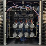
Here’s the completed F4 which already proved to play very nice but until today never got its frontplate finished…
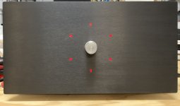
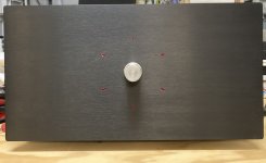
Since Zm mocked me I built a nice washing machine!, I added a switch we here know from the wash-machine-installation—it turns on/off in both directions (360°)
Here’s the completed F4 which already proved to play very nice but until today never got its frontplate finished…
Since Zm mocked me I built a nice washing machine!, I added a switch we here know from the wash-machine-installation—it turns on/off in both directions (360°)
Attachments
-
 741091C1-FFBB-4F81-A89E-934348740AA9.jpeg737.1 KB · Views: 461
 -
 CF108831-25A4-4809-AE44-FF654369A500.jpeg202.2 KB · Views: 470
 -
 1FB9E7BB-9082-420B-B9C7-DEB0CD825AB6.jpeg666.7 KB · Views: 403
 -
 D696C242-2957-47D9-83E8-554215E2733B.jpeg263.9 KB · Views: 391
 -
 4C90ED61-A027-4DD4-BB23-98F6BE12DB0E.jpeg472.1 KB · Views: 360
 -
 D666AE3F-E3E7-4F62-A839-1CC4F3B22727.jpeg510.8 KB · Views: 346
 -
 50848FC3-1F33-42F4-A0F3-FC6F3B0182DA.jpeg525.8 KB · Views: 449
It indicates the amp is on?

Soft-start-led, psu-led and amp-led all on deck!
(Pure fancyness because @JMFahey once stated that mechanics without machines begs for precision to the 1/10 mm, so I had to know. And it’s fancy starwars-deathstar-groove… don’t think I'd do it again though)
Soft-start-led, psu-led and amp-led all on deck!
(Pure fancyness because @JMFahey once stated that mechanics without machines begs for precision to the 1/10 mm, so I had to know. And it’s fancy starwars-deathstar-groove… don’t think I'd do it again though)

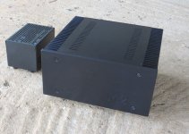
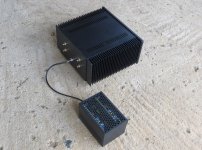
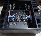
My M2 clone built from Teabag's boards. Yeah, it took that long... 
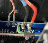
Two SMPS housed in a custom enclosure and connects to the amp via 4-core cable and 5-pin audio connectors. The 4th wire in the cable is for the earth wire.
Two SMPS housed in a custom enclosure and connects to the amp via 4-core cable and 5-pin audio connectors. The 4th wire in the cable is for the earth wire.
Attachments
External power supply is great idea. Can be used with F4, F5, AlephJ, many others...My M2 clone built from Teabag's boards. Yeah, it took that long...
Two SMPS housed in a custom enclosure and connects to the amp via 4-core cable and 5-pin audio connectors. The 4th wire in the cable is for the earth wire.
Yes, you're right. I haven't even thought of that. Hmm... maybe an AlephJ next.External power supply is great idea. Can be used with F4, F5, AlephJ, many others...


Hi
@myleftear , what the width of the chassis used ? Is it something like "mini dissipate" or ... smaller ? It seems tight in there...

@myleftear , what the width of the chassis used ? Is it something like "mini dissipate" or ... smaller ? It seems tight in there...
Yes, it’s a mini dissipante, 4U high, 330(?) wide and yes, it is tight in there… (but it’s also big parts! (My next amp, old soul, is in a mini dissipante 3U and has a dual mono psu… (but no extras like spkrprot/softstart)
Back then, the chassis was a prototype/custom made, I believe it is available through the modushop store now.
Back then, the chassis was a prototype/custom made, I believe it is available through the modushop store now.
1) Thanks @myleftear. I am starting to consider building an M2x (started to order components,... might take a while to get everything), and i would have gone with Mini Dissipante 330 wide external 250mm internal due to space constraints in the rack/space i have. Now, i am .... slightly reconsidering the future box! (and location of the amp). I would go with transformer inside, bridget rectifiers & banks of cap.
From your pictures (very helpful!), it will be (very) tight also.
I will be careful to "prototype" on a board with the future case's constraints, to later see how i would go.
2) If you can tell how is the heat dissipation in this enclosure i would be very interested.
Have a nice day
From your pictures (very helpful!), it will be (very) tight also.
I will be careful to "prototype" on a board with the future case's constraints, to later see how i would go.
2) If you can tell how is the heat dissipation in this enclosure i would be very interested.
Have a nice day
Last edited:
Hi rif@skylplease provide pix and details of the stand-alone PS. A great idea!
I’m not sure if you want details of the separate PS enclosure or the PS itself, so I’ll include as much as I can. Please excuse if I post information that you already know.
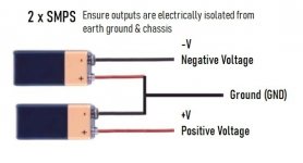
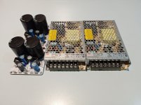
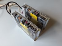
The first picture shows how two power supplies can be connected together to provide +V and -V. The following pictures show the two Meanwell LRS-150-24 that I’ve used – turned on it’s sides and covers removed inside the enclosure. I had to adjusted the voltage higher than 24V to account for the voltage drop in the capacitor multipliers that I am using. After the Cap Mx, the voltage is 24V – as required by the amp.
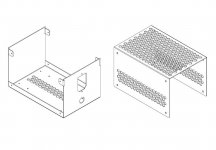
The drawing shows the two parts of the enclosure that I had laser cut and bent at a local sheetmetal workshop. The finish is coarse powder coating and it looks really good and professional. All my friends asked where I bought it.
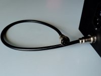
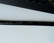
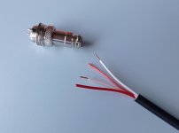
The connecting cord is 4-core Tachii T-4S6 with outside diameter of 6mm which fits neatly in the 5-pin M16 audio connectors. The length of the umbilical cord has been kept short since it’s carrying DC. I made it 50cm long including connectors.
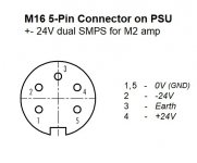
The next picture shows the pinout of the connectors. You’ll notice that GND is spread over two pins since it serves as GND for both +V and -V. The pins of these connectors are rated 5A and I didn’t want to overload a single GND pin by using a 4-pin connector. BTW, the M2 draws 160W total and presumably half of that is supplied by +V and the other half by -V. That means each pin carries about 3A at the 27.4V that I set the PS’s to. The cable and connectors all seem quite happy dealing with the load.
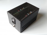
The last picture shows the completed PS enclosure with IEC socket + switch and the umbilical connector.
Please refer to the post below by XRK971 on how he did the same thing. It contains important information that you should heed.
https://www.diyaudio.com/forums/solid-state/344540-alpha-nirvana-39w-8ohm-class-amp-post6185905.html
Attachments
-
 Pos_neg_smps.jpg25.9 KB · Views: 277
 -
 IMG_20211018_223529.jpg258.6 KB · Views: 256
 -
 IMG_20211106_133336.jpg204.9 KB · Views: 253
 -
 Drawing.jpg90.6 KB · Views: 237
 -
 2022-02-14_14-30-52.jpg214.2 KB · Views: 221
 -
 2022-02-14_14-24-10.jpg242.8 KB · Views: 228
 -
 IMG_20211111_150557.jpg154 KB · Views: 214
 -
 PSU Connector.jpg29.8 KB · Views: 244
 -
 IMG_20211122_123217.jpg188 KB · Views: 264
- Home
- Amplifiers
- Pass Labs
- Pictures of your diy Pass amplifier