Pass DIY Addict
Joined 2000
Paid Member
Thank you!
.
.
.
.
What the hell is "fugly"?
IS FXXXXing ugly
Every body know that

Some how became coveted prize comment from Numero Uno poster(POSTER person that has loads n' loads n' loads n' loads of time to post posts when he is not sitting on cement pole) here in Papa Land
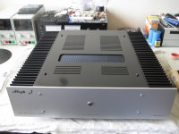
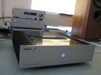
Aleph J finally finished...
I promised to post more pics when the top plate and frontpanel were done.
So here you are...
Walter
I promised to post more pics when the top plate and frontpanel were done.
So here you are...
Walter
Attachments

Aleph J finally finished...
I promised to post more pics when the top plate and frontpanel were done.
So here you are...
Walter
Very nice work Walter!
Could you tell me how the mesh in the top cover is attached?
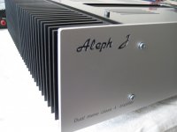
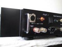
Is the pushbutton/eye in front connected to an Ebay soft start like you used in the other builds?
Thanks for sharing your work with us.
Nash
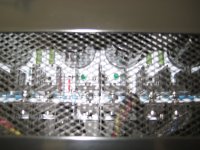
The mesh is attached with 3M VHB bonding tape. Very strong stuff... And also on the four edges some dots with the glue gun. To seal the bonding tape, I put some ordinary black tape over it.
The mesh is right above the 16 x BYW99 rectifiers with heatsinks and they run pretty hot. Around 60C at the heatsink.
Push button is connected to a red Ebay soft start indeed. Same as in F5Tv3.
Walter
The mesh is right above the 16 x BYW99 rectifiers with heatsinks and they run pretty hot. Around 60C at the heatsink.
Push button is connected to a red Ebay soft start indeed. Same as in F5Tv3.
Walter
Pass DIY Addict
Joined 2000
Paid Member
The mesh is attached with 3M VHB bonding tape. Very strong stuff... And also on the four edges some dots with the glue gun. To seal the bonding tape, I put some ordinary black tape over it.
The mesh is right above the 16 x BYW99 rectifiers with heatsinks and they run pretty hot. Around 60C at the heatsink.
Push button is connected to a red Ebay soft start indeed. Same as in F5Tv3.
Walter
Thanks for the tip on the VHB tape. I will use it on my next project.
Is the power for the LED portion of the pushbutton from the PSU board or from the red Ebay softstart?
Nash
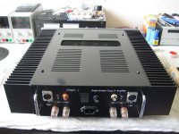
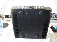
Where did you get those heatsinks? They look great and I've always envisioned a pair of low height mono blocks just like that!! Outstanding!!
Hi MASantos: https://www.distrelec.nl/elfa3~nl_nl/elfa/init.do?item=75-626-71&toc=20476
- Home
- Amplifiers
- Pass Labs
- Pictures of your diy Pass amplifier