I have been known to post pictures of disgusting lash-ups (although not on this thread).
Here's a picture of a pre-amplifier I built.
It uses 955 acorn triodes in differential pairs with 6AW8A triode pentodes as combined cathode followers and pentode sinks.
On test the circuit worked well: -3dB at 180kHz and low distortion.
I have never built the power supply so don't ask how it sounds!
The knobs are from RCA AR88 radio and the Nixie tube (which just shows input selection) came (complete with its 12-pin socket) from a redundant Solartron voltmeter.
I have a snap of the underside if anyone would care to see about thirty miles of wires...
7N7
rdf said:Sweet! I love the 955 and stocked up bigtime, sockets too. The cheater version 9002 currently has a home CCS-loaded as the front end of my little 6CW5 SE.
Yes, the sockets are a bit difficult - fortunately I have some - other than the ones in the amp shown.
Just looking at 6AW8A in another job...
I should have built an all RCA amp when I had the chance: 955s/3C33/829Bs!
By the way, that avatar is great!
7N7
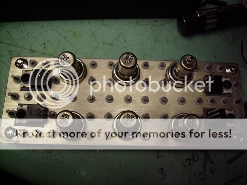
Hey all. Really enjoy seeing everyone's projects and thought I would share something I'm working on.
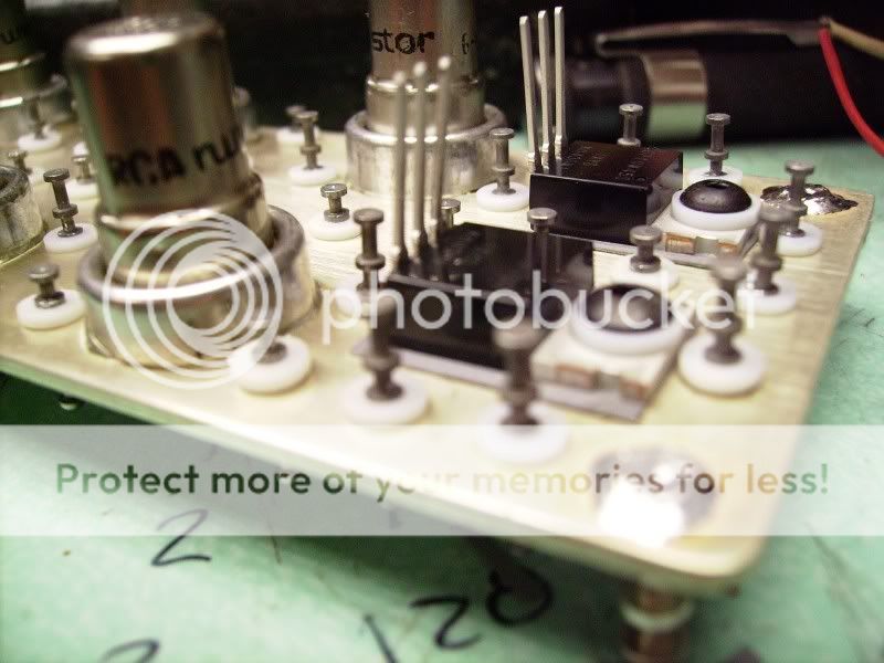
This is a bit of a work in process, I'm designing a single channel tube preamp with constant current sources for my senior project for my EE degree (Cal Poly). I just finished building the board today, which is a 0.125" thick piece of sheet brass, silver plated, with Teflon press-fit solder terminals.
The preamp is going to be used with my mandolin pickup (it's a balanced electrodynamic transducer made by Schertler) for playing live gigs. The final configuration will have a gain control on the box itself and a volume pedal, both of which control the gain of the front end (differential cascode with 8393 Nuvistors). Output stage is push-pull with a Lundahl transformer.
rdf said:Lees Radio in New York still stocked NOS ceramic acorn sockets at a fair price not long ago. Some of the pentode acorns are also interesting, as are the DHTs (100 ma filaments!) I've toyed with the notion of an all-acorn w/ pentode CF-out pre for a long time.
That is interesting - I should like to hear more about this if you build it; I have been helping a friend (and fellow member) with a DHT project - apart from 813 and 845, my first contact with the genre!
7N7
Nice amp you are building...looks like it is built to withstand a nuclear bomb! I like it...Hey all. Really enjoy seeing everyone's projects and thought I would share something I'm working on.
Bas Horneman said:
Nice amp you are building...looks like it is built to withstand a nuclear bomb! I like it...
Thanks! I got into the habit of building things to be as bomb-proof as possible... I get tired of messing around with perfboard. Yeah, it might be a little overkill but it sure looks purty.

As for a nuclear bomb? The chassis and the nuvistors would probably be OK... not sure about those IXYS current regulators, though! ;-)
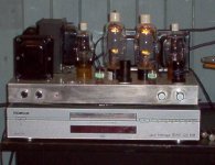
My old, main amp lost a power transformer so I put together this little one to hold me over while I build my new main amp. It uses iron from an old integrated - Scott 222C. This amp used 7189 output tubes and was rated for 24 watts.
I ditched the tube rectifier (the whole schematic really!) for solid state and raised B+ from 420V to 505V. I used EL34s and 12au7 tubes. This is not UL - it's straight pentode mode. I know the 12au7 has a bad rep - but i don't buy in, I think it's a magical tube when used properly. I think most can't deal with it's lack of gain. The amp is very solid from top to bottom and sounds great. Cheap too! Enjoy!
I ditched the tube rectifier (the whole schematic really!) for solid state and raised B+ from 420V to 505V. I used EL34s and 12au7 tubes. This is not UL - it's straight pentode mode. I know the 12au7 has a bad rep - but i don't buy in, I think it's a magical tube when used properly. I think most can't deal with it's lack of gain. The amp is very solid from top to bottom and sounds great. Cheap too! Enjoy!
An externally hosted image should be here but it was not working when we last tested it.
An externally hosted image should be here but it was not working when we last tested it.
FastEddy said:Cycline3: Curious about your sub woofer / pre-amp splitter circuit ... Separate amp or parasitic from your main amp ?? (Got schemo?)
The preamp is a zero negative feedback design. The first tube provides gain and then the signal is split into the 2 sections of the second tube. Both sections are cathode followers to drive the cables/output. One is the pre out to the amp, the other is a subwoofer line out that goes to the sub. That way the load of each does NOT interfere with each other. It's got a tube regulated power supply to drive it all. It sounds sweet. And no schematic to post for now... sorry! It's on my list of things to do one day, draw them all up nice and pretty so.. who knows?
I'm with you... yes the sub has a crossover built in. It is set at just under 50hz and very low volume. The 703s are rated to 38 and have really nice bass all on their own. The sub is barely working and fills in that bottom octave quite nicely.FastEddy said:... I assume that the "stand alone" sub amp has low pass filter built in? (another scenario?)
" ... The sub is barely working and fills in that bottom octave quite nicely. ..."
Good show. I hate too much bass, but my planar mains roll off around 120 htz, so I gotta have something to fill out the bottom end.
( I'm rebuilding my system this week = tube pre-amp feeding 400 watts power MOSFET amp for the two mains, 150 watts for the sub woofer ... and I have the gain set about 3 db down on the sub. A DIY summing op-amp combines both main channels from the pre-amp for the single channel sub amp and includes the low pass filter set to around 120 Htz. )
Good show. I hate too much bass, but my planar mains roll off around 120 htz, so I gotta have something to fill out the bottom end.
( I'm rebuilding my system this week = tube pre-amp feeding 400 watts power MOSFET amp for the two mains, 150 watts for the sub woofer ... and I have the gain set about 3 db down on the sub. A DIY summing op-amp combines both main channels from the pre-amp for the single channel sub amp and includes the low pass filter set to around 120 Htz.
)tube system
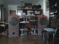
A strange system with vacuum tubes topologies . Preamplifier with 801 RCA tubes [15db gain], pnono stage MC [ECC83 and j fet], line preamplifier with 250TH tubes [15db gain], line preamplifier with 6J5 and 6SN7 tubes , Two power amplifiers with 250TH tubes SE A2 60 watts/ch , and two power amplifiers with 6DQ6 tubes in triode mode pp 30 Watts/ch . The loudspeakers are with Focal drivers 92db/W .
A strange system with vacuum tubes topologies . Preamplifier with 801 RCA tubes [15db gain], pnono stage MC [ECC83 and j fet], line preamplifier with 250TH tubes [15db gain], line preamplifier with 6J5 and 6SN7 tubes , Two power amplifiers with 250TH tubes SE A2 60 watts/ch , and two power amplifiers with 6DQ6 tubes in triode mode pp 30 Watts/ch . The loudspeakers are with Focal drivers 92db/W .
Attachments
Re: tube system
The ports look on the small side for size of drivers. ?
richj
Originally posted by gianis The loudspeakers are with Focal drivers 92db/W . [/B]
The ports look on the small side for size of drivers. ?
richj
- Home
- Amplifiers
- Tubes / Valves
- Photo Gallery