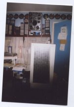
Here is the magnet array on the speaker in question, they have holes, no particular reason. that's what was available at the time. I used a aluminium rod to keep magnets straight and apart in the vertical direction. I used perforated steel sheet to hold the magnets and lined the cutout with draught proofing tape. Fill the cutout as much as possible with magnets. Use a trapezoid shape for the cutout. Standing waves??
Attachments
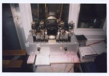
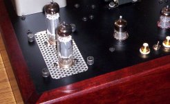
Lasarus, transformer coupled monoblocks
One of two monoblocks:
Transformer coupled push pull amplifier bases on KR-Audio’s 842VHD direct heated triodes and EL84 driver stage.
Schematic:
The amp gives 40W rms in class A, 60W in class AB1 and some more power when forced into class AB2.
Frequency response: <10Hz-50kHz (-3.5dB), 20Hz -20kHz (+/-0.2dB)
Distortion: at 40W: 0.12% 2HD, 0.12% 3HD, at 55W: 0.3% 2HD, 0.3% 3HD.
Output impedance: 0.9 ohm, DF: 9
Distortion pattern at 55W rms:
Tubes and stuff from www.demostenes.no
Transformers from www.sowter.co.uk
Chassis work by www.mapletreeaudio.com
Jan E Veiset
Norway
One of two monoblocks:
An externally hosted image should be here but it was not working when we last tested it.
Transformer coupled push pull amplifier bases on KR-Audio’s 842VHD direct heated triodes and EL84 driver stage.
Schematic:
An externally hosted image should be here but it was not working when we last tested it.
The amp gives 40W rms in class A, 60W in class AB1 and some more power when forced into class AB2.
Frequency response: <10Hz-50kHz (-3.5dB), 20Hz -20kHz (+/-0.2dB)
Distortion: at 40W: 0.12% 2HD, 0.12% 3HD, at 55W: 0.3% 2HD, 0.3% 3HD.
Output impedance: 0.9 ohm, DF: 9
Distortion pattern at 55W rms:
An externally hosted image should be here but it was not working when we last tested it.
Tubes and stuff from www.demostenes.no
Transformers from www.sowter.co.uk
Chassis work by www.mapletreeaudio.com
Jan E Veiset
Norway
Nice looking amp Jan, looks a lot better than my amps, still I don't have to please a wife! Do you? I've never come across these output valves before! Is that a bias meter I see? What does it sound like and what speakers do you use with it? Can't get over how gorgeous it looks you must have spent a fortune on the transformers and chassis!!. I've put another one of my amps on. Using CV57's P/P about 500v. I couldn't afford intermediate transformers so I used 4 cheap output transformers instead, which I read about in the book :-Audio Frequency Amplifier Design by GEC.
Attachments
Thank you JAMESBOS!
My speakers are Klipsch RF5 and WLM Diva and yes I’ve got a wife")
There is a typo in the specifications, the output impedance is too good to be true, the real value should be 2 ohm.
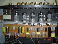
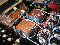
A picture from the inside:
Jan E Veiset
My speakers are Klipsch RF5 and WLM Diva and yes I’ve got a wife
There is a typo in the specifications, the output impedance is too good to be true, the real value should be 2 ohm.
A picture from the inside:
An externally hosted image should be here but it was not working when we last tested it.
Jan E Veiset
Regards Jan
They look even better on the inside, how do you do it? Mine look like spaghetti after it been hit by a bomb or several!!! I can't afford speakers like that so had to make my own IB's, Underfloor Loaded, Transmission line and full range planar speakers, using ferrites and neo's. I also built several amps, some worked some didn't but the ones that did, Iam quite happy with and it keeps me out of trouble. Being retired (68), it keeps me busy and active. Henry.
They look even better on the inside, how do you do it? Mine look like spaghetti after it been hit by a bomb or several!!! I can't afford speakers like that so had to make my own IB's, Underfloor Loaded, Transmission line and full range planar speakers, using ferrites and neo's. I also built several amps, some worked some didn't but the ones that did, Iam quite happy with and it keeps me out of trouble. Being retired (68), it keeps me busy and active. Henry.
Very nice Jan! What do you use as a control amp to drive it? How do you bias the output tubes? You did not show the PS schematic. Are you using four TV damper tubes as the PS bridge?
The output tube filaments look dark in your picture yet all other tubes are in glorious glow. Is this a standby mode or something?
Again very nice construction.
The output tube filaments look dark in your picture yet all other tubes are in glorious glow. Is this a standby mode or something?
Again very nice construction.
I'm using a preamp with a 6J5 common cathode gain stage with a 6R7 cathode follower. Since I've got ~20dB gain in the preamp I don't need high sensitivity power amps. 3V rms input for full tilt was the design target.
The output tubes are running at ~480V/80-90mA cathode bias each. You’ll find the complete schematic here: http://www.veiset.net/842/R070201.gif
The filaments in the 842s don't glow too much and most of the filament is hidden behind the plate.
Jan E Veiset
The output tubes are running at ~480V/80-90mA cathode bias each. You’ll find the complete schematic here: http://www.veiset.net/842/R070201.gif
The filaments in the 842s don't glow too much and most of the filament is hidden behind the plate.
Jan E Veiset
A picture from the inside:
That looks very nice. Where do you find the (looks like blank?) PC boards with connection posts along the edges, that you've mounted most of the components on?
qq:
>Where do you find the (looks like blank?) PC boards with connection..
You almost spelled it: Partsconnexion.com
rdf:
>The KR site doesn't show plate curves for the 842VHD, did you generate your own set?
No, I’ve got the plate curves that followed each tube:
>the B2+ bypass cap is shown in 'bang polarity'.
Whoops! I should fix that.
Jan E Veiset
>Where do you find the (looks like blank?) PC boards with connection..
You almost spelled it: Partsconnexion.com
rdf:
>The KR site doesn't show plate curves for the 842VHD, did you generate your own set?
No, I’ve got the plate curves that followed each tube:
An externally hosted image should be here but it was not working when we last tested it.
>the B2+ bypass cap is shown in 'bang polarity'.
Whoops! I should fix that.
Jan E Veiset
... Jane = drinkin' the good stuff ... http://www.veiset.net/eOTL/upper10logo.jpg
I may have to seek some of this as well ... maybe my poor efforts will improve.
I may have to seek some of this as well ... maybe my poor efforts will improve.
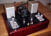
planet10 said:Now that you've posted the tease, let's see one of the whole amp...
dave
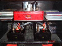
A little more. I'll try to get a shot with the lights off and no flash.
Attachments
- Home
- Amplifiers
- Tubes / Valves
- Photo Gallery