The 'gain' comes from the little black box rear left? Thanks for reminding me of that chassis option, looks great.spud
Thank you, I have many such works.SVStube, nice work there, especially impressed with the chassis, how did you print the lettering?
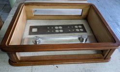
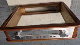
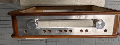
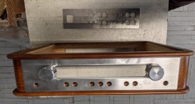
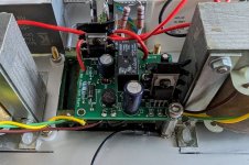
The photo shows the details of the case of a similar amplifier. Details with inscriptions are all flat, and can be printed on a flatbed printer.
Attachments
Hi Andy.Thanks SV. A good flatbed printer seems to be a good bit of kit to get if making DIY amps. BTW, do you hand fabricate your metal work and what software do you use to design the printing?
Any advertising firm has a good tablet printer. I make an order there.
Body parts, metal or wood, I also order from professionals.
Software FrontDesigner_3.0.
Serhii.
Just wow,Im new to this forum. My name is Aldo. I wanted to introduce myself and share my latest project. I made the cabinet out of a single sheet of popular hardwood and the electronics are a 5F6A clone
If that was in my living room, wouldn't have to even turn it on for accolades from guests
The wood capsule is heavy and deep- this coming from a metal guy

Jim
It's not finished, but as a complete and total newb i wanted to post SOMETHING here lol.
Im working on a preamp built around 6AG5 (and 6au6 too once i add a 4ohm variable resistor to the heater circuit for fine tuning, prob test points for rear of a chassis too)
the current work bench tinker toy version is a complete rats nest pile. But the performance im getting out of the thing is pretty on point. I've preferred its character compared directly against far more expensive preamps now A/B. And i could not be happier with the circuit. Almost ready to build one that isn't a total pile.
Sorry for ugly solder joints and rat nesty wires, its a prototype thats been re-soldered/changed around heavily It'll look nice again some day

Im working on a preamp built around 6AG5 (and 6au6 too once i add a 4ohm variable resistor to the heater circuit for fine tuning, prob test points for rear of a chassis too)
the current work bench tinker toy version is a complete rats nest pile. But the performance im getting out of the thing is pretty on point. I've preferred its character compared directly against far more expensive preamps now A/B. And i could not be happier with the circuit. Almost ready to build one that isn't a total pile.
Sorry for ugly solder joints and rat nesty wires, its a prototype thats been re-soldered/changed around heavily
It'll look nice again some day

Fuling,
I would say those look beautiful.
It seems that they deserve a "Glowing" report.
Your description tells most of the story. But what you did, and how, to make it Class A2 is of interest (many ways to do that; which one?)
Would you share a schematic, please?
I built a Class A1 SE Triode wired 807 low power mono-block.
Low plate dissipation, just for hot summer days.
Thanks!
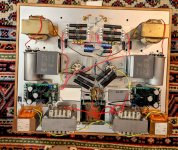
I hope I can take better pictures later when they´re finished, they still miss some parts (cathode decoupling caps for the input stages) and some resistors are to be replaced. The teak frames will be coated with shellac before the final assembly.
No schematic yet, but the circuit is quite simple: Triode wired 6SJ7, cap coupled to a choke loaded 6E5P cathode follower which is direct coupled to the output tube. A Mosfet would probably make a better follower but I like the vintage approach and slow startup that I get from a tube, and I'd say 6E5P is one of the better choices for a cathode follower.
The output stage uses ~3dB of CFB from the 16R tap on the secondary.
- Home
- Amplifiers
- Tubes / Valves
- Photo Gallery