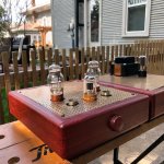
What type of media player is that?
Why did you need to use wooden compartments?
Do you want to show your schematic?
Volumio/HifiBerry/Raspberry Pi inside.
Aluminium top plate glued to Ikea tray=The IKEA tray comes like that with the wooden compartments. The schematic is a MK1 RH84
Nice job! I think we all get caught up thinking in a 2D plane sitting on a shelf. Along with good use of space, it allowed you to keep the signal at the top well away from noisy parts of power supplies.Space is an interesting topic. I’ve chosen to eliminate the space a table/rack takes up. The inside pair are umbilical joined, the outer pair are mono blocks. There’s room for more 🙂
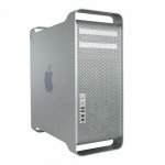
I have been gathering parts to build a PP EL84 in a similar format (which i really like) using the aluminum PowerMac/MacPro enclosure (i have spares if anyone wants them).
dave
Attachments
 Well heck ya I'm interested
 I would have never guessed such sound could come from such a small, elegant design.
Space is an interesting topic. I’ve chosen to eliminate the space a table/rack takes up. The inside pair are umbilical joined, the outer pair are mono blocks. There’s room for more 🙂
These chassis’s present around 550 square inches by 4 or 5 inches deep and I use it all. Lots of iron in my favored designsShort signal path up top but the power supply is spread out some. I live away from the city so FM/ radio is no big deal. Amps are quiet.
Jeeezz, the whole setup looks very good to me!
The outer units seem left-right mono amps isn't it?
But the inner two units are each of different type seems to me anyway. Am I correct?
Member
Joined 2009
Paid Member
I have been gathering parts to build a PP EL84 in a similar format (which i really like) using the aluminum PowerMac/MacPro enclosure (i have spares if anyone wants them).
dave
that sounds like a nice project and already has a cool looking chassis!
P-10, Dave, it’s the 10.3. I broke them in for an entire summer before the build. Taking one’s time usually pays dividends 🙂 I’m every time amazed by how coherent the sound is even though the numbers might say not! ‘Beautiful use of that back wave 😎
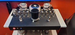
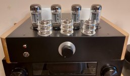
That inner pair with the solid metal fronts are a separated PSU and signal section. The PSU is inductor input with a bridge rectification using 866A mercury vapor rectifiers. The signal section is EML 20A driving a JJ 2A3. It’s a unique design by James Dowdy, a frikin’ genius!
That inner pair with the solid metal fronts are a separated PSU and signal section. The PSU is inductor input with a bridge rectification using 866A mercury vapor rectifiers. The signal section is EML 20A driving a JJ 2A3. It’s a unique design by James Dowdy, a frikin’ genius!
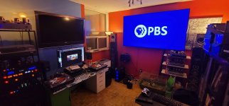
It takes some effort to pull off 6 amplifiers and 4 sets of speakers all switchable
Best part? Setting it and forgetting which amp is in circuit... (I have a terrible short term memory!)
Grey and Nigel say hi! (guinea pigs)
PBS FTW but it was a coincidence...
Best part? Setting it and forgetting which amp is in circuit... (I have a terrible short term memory!)
Grey and Nigel say hi! (guinea pigs)
PBS FTW but it was a coincidence...
Attachments
Last edited:
It takes some effort to pull off 6 amplifiers and 4 sets of speakers all switchable
Best part? Setting it and forgetting which amp is in circuit... (I have a terrible short term memory!)
Grey and Nigel say hi! (guinea pigs)
PBS FTW but it was a coincidence...
Is this whole set up part of your living room?
Thanks, Andy.
Mine are switched by Phoenix Contact relays...
Yes it is, Joe. I live in a bachelor apartment. The other side is where the bed and "workshop" is.
Ahhh! I thought so, my wife would refuse such kind of setup in our living room. But to be honest, I am a tiny, tiny little bit jealous.....
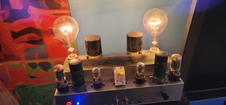
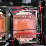
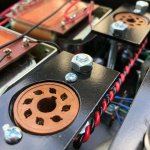
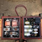
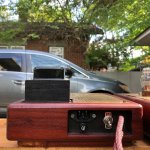
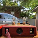
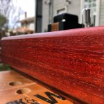
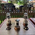
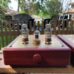
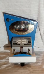
Headphone amp for 1626 output tube using Bob Danielak’s classic “Darling” circuit, switchable with the later “Clementine” variant by inserting 8532 or 6SL7 input tube. Lundahl LL2765 OPTs, vintage PIO coupling caps, and carbon comp grid leak resistors contribute to its involving musical sound. I modified Bob’s design by employing a separate cathode network in each channel, rather than a common one shared by both. It sports a dual chassis of African padauk finished with Danish oil and lacquer. One shielded umbilical carries the 6.3V and 12.6V AC heater supplies while the other carries the HT voltage and signal ground; both carry the chassis ground via the shields and a conductor. I designed a power supply with the type 80 rectifier into a double pi filter with 10h chokes and oil-filled motor run caps. It’s only begun breaking in but sounds excellent so far. I listened to Radiohead’s “House of Cards” 4 or 5 times last night.
Attachments
-
 6FC702AF-E1CB-4403-8FEA-6A593DC0143E.jpeg517.2 KB · Views: 296
 -
 38622884-E778-4BB5-8B95-D701889A6612.jpeg323.4 KB · Views: 406
 -
 DEBA47A8-4561-4296-86E1-50F2AABB283B.jpeg743.8 KB · Views: 409
 -
 C9483F67-4610-48E7-B2E7-7C328D277171.jpeg432.2 KB · Views: 300
 -
 2F2D4D00-4892-463B-8AAA-C77C923FF0E6.jpeg388.2 KB · Views: 782
 -
 098AECDB-5849-4C14-8B1F-B1D47914E48D.jpeg349.7 KB · Views: 812
 -
 68D4FA65-EE85-4C5A-84CC-72C1810A3714.jpeg582.2 KB · Views: 816
 -
 04998071-FA63-4A16-811F-D9D11F7C4633.jpeg425.2 KB · Views: 838
 -
 14BDBA97-2CFD-4AF3-8605-8F3D786F499B.jpeg436.2 KB · Views: 861
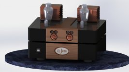
I am repackaging my 300B SET amp. Found these 2 chassis on AliExpress that will fit everything. Thinking of 3d printing the badge out of metal and filling the while in with this pseudo porcelain powdered stuff. I have done this before and it works really well.
Wanted to get some input and see if anyone has any better ideas. I am using tiny nixies for the volume indication. I have 2 knobs because I am using a pair of Intact audio autoformers.
So if anyone has any ideas to improve upon this please share..
Jeff
Wanted to get some input and see if anyone has any better ideas. I am using tiny nixies for the volume indication. I have 2 knobs because I am using a pair of Intact audio autoformers.
So if anyone has any ideas to improve upon this please share..
Jeff
Attachments
It takes some effort to pull off 6 amplifiers and 4 sets of speakers all switchable
Best part? Setting it and forgetting which amp is in circuit... (I have a terrible short term memory!)
Grey and Nigel say hi! (guinea pigs)
PBS FTW but it was a coincidence...
Put those guinea pigs to work!!... power generating wheel in their future?
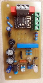
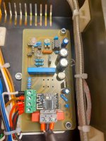
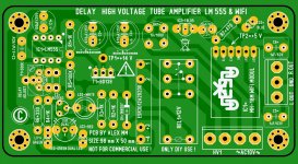
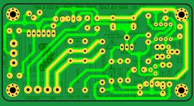
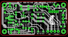
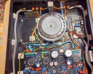
HV delay, and Bluetooth, was the wish, of customer . I layout, a small PCB for this requirement . I't work well, time adjusted to 40 seconds . Relay changed to SSR the blue one .
Regards,
Alex
Regards,
Alex
Attachments
-
 20210421_164353-001.jpg824.8 KB · Views: 359
 -
 20210509_215112-001.jpg323.6 KB · Views: 291
 -
 20210509_222659-001.jpg643 KB · Views: 255
 -
 PCB DELAY+WIFI PIC TOP-001.jpg418.4 KB · Views: 254
 -
 PCB DELAY+WIFI PIC BOTTOM-001.jpg316.4 KB · Views: 179
 -
 PCB DELAY+WIFI ALL COLOR-001.jpg449.2 KB · Views: 178
 -
 20210509_231150-001.jpg1 MB · Views: 259
- Home
- Amplifiers
- Tubes / Valves
- Photo Gallery