Member
Joined 2009
Paid Member
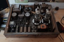
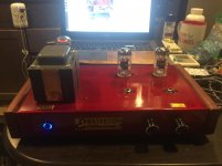
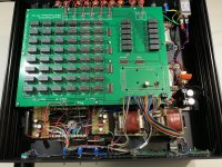
814A PP monoblocs.
love it !
"hey ma, look what I found in the garden shed" !
Thank you for your kind words..
Far from perfect but ok for me, no spray, only a small pencil and hammerite paint.
It takes some time..
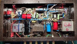
Bridge rectifier made with 16 x D302 Ge diodes and balancing resistors.
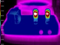
The venerable EF80 is wired as a diode between wiper and ground of negative supply. At switch on 814's current is about 14mA then 56mA after EF80 conduction.
Far from perfect but ok for me, no spray, only a small pencil and hammerite paint.
It takes some time..
Bridge rectifier made with 16 x D302 Ge diodes and balancing resistors.
The venerable EF80 is wired as a diode between wiper and ground of negative supply. At switch on 814's current is about 14mA then 56mA after EF80 conduction.
Attachments

Thank you for your kind words..
Far from perfect but ok for me, no spray, only a small pencil and hammerite paint.
It takes some time..
Bridge rectifier made with 16 x D302 Ge diodes and balancing resistors.
The venerable EF80 is wired as a diode between wiper and ground of negative supply. At switch on 814's current is about 14mA then 56mA after EF80 conduction.
very nice work indeed.
Those two rotary switches where did you purchase these?
Those two rotary switches where did you purchase these?
I dismantled bakelite loctal sockets to use them as supports for the two pots (wirewound multiturns 5K & 50K)
Like this:
https://i.ebayimg.com/images/i/381116692776-0-1/s-l1000.jpg
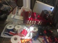
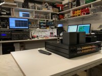
Finishing assembly of the first pre-production Preamp+ in my trailer. I still have few available layers of space to keep parts and tools. 
Well; it looks like everything is properly connected now. Let's power it on and check that no magic smoke escapes. You know that electronic devices stop working if the magic smoke escapes from them, right?
Well; it looks like everything is properly connected now. Let's power it on and check that no magic smoke escapes. You know that electronic devices stop working if the magic smoke escapes from them, right?
Attachments
Yes. In Canada, some forms of magic smoke are legal. ��
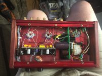
Well; it did not escape.
Attachments
Finishing assembly of the first pre-production Preamp+ in my trailer. I still have few available layers of space to keep parts and tools.
Well; it looks like everything is properly connected now. Let's power it on and check that no magic smoke escapes. You know that electronic devices stop working if the magic smoke escapes from them, right?
Like the color! I also use this red color for my preamps!
kuly,
That amplifier looks nice, it should sound great.
So which tube is it?
6N1P
u = 33, Gm = 4400 uMhos, rp 7500 Ohms. Filament 600mA @ 6.3V
(Taken from the Svetlana data sheet tube curves).
Unfortunately, the numbers on that data sheet are Gm 7500 uMhos, rp 4400 Ohms (Reversed or Swapped, a Typing error?).
The tube curves, and the numbers do not agree.
But, these specification are not the same as an ECC81.
ECC81
u = 60, Gm = 5500 uMhos, rp 11000 Ohms. Filament 300mA @ 6.3V
Looks like a 12AT7 to me.
I do see your picture, seems to be using an ECC81, or an ECC83 (it is hard to read the last number from your photo).
I have used 6N1P, ECC81, and ECC83. They are all different from each other.
Last edited:
Cleo 7
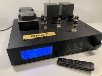
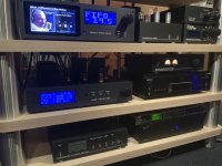
I just finished my 6N30P MU-Stage pre amplifier. It is called the Cleo 7 (for those who remember the tube amps from Triodedick )
This version has an Arduino controlled GPIO, bias checking and Volume Control on board. Front panel and IR remote driven.
here you can read all about it including circuits, pictures, measurements and Arduino Code
Check my blog website on the Cleo 7
next project is true Tape playback Head amplifier based on Mu-Follower
.
I just finished my 6N30P MU-Stage pre amplifier. It is called the Cleo 7 (for those who remember the tube amps from Triodedick
)This version has an Arduino controlled GPIO, bias checking and Volume Control on board. Front panel and IR remote driven.
here you can read all about it including circuits, pictures, measurements and Arduino Code
Check my blog website on the Cleo 7
next project is true Tape playback Head amplifier based on Mu-Follower
.
Attachments
Last edited:
Thank you for your kind words..
Far from perfect but ok for me, no spray, only a small pencil and hammerite paint.
It takes some time..
Bridge rectifier made with 16 x D302 Ge diodes and balancing resistors.
The venerable EF80 is wired as a diode between wiper and ground of negative supply. At switch on 814's current is about 14mA then 56mA after EF80 conduction.
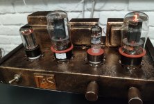
Beautiful!
Very industrial looking.
Nice work!
I wish my shop was that clean and organized.
I wish my shop was that clean and organized.
I just finished my 6N30P MU-Stage pre amplifier. It is called the Cleo 7 (for those who remember the tube amps from Triodedick
This version has an Arduino controlled GPIO, bias checking and Volume Control on board. Front panel and IR remote driven.
here you can read all about it including circuits, pictures, measurements and Arduino Code
Check my blog website on the Cleo 7
next project is true Tape playback Head amplifier based on Mu-Follower
.
kuly,
Most driver circuits do not have the optimum parameters for both the 6N1P and ECC81.
Some adjustment is necessary for optimum performance.
But, with reasonable circuit resistances, both the 6N1P and ECC81 should be able to drive a 6P3S or 6L6 to maximum output level (With the output tube biased typically at 15 or 20V).
Is that the bias voltage you use on your 6P3S?
That only requires 30V peak to peak, or up to 40V peak to peak.
- Home
- Amplifiers
- Tubes / Valves
- Photo Gallery