I like it.I am at home for 30 days for this virus so lots of time, so I decide to give it a go to the Rickard Berglund design.
I already order most of the components moths ago, still waiting the power transformer from Antek and the 3U rack mount cabinet all bought in US so I really do not know when they will arrive here in Philippines with this crisis, so with all I have and using a power transformer used for a tube amp I start the project.
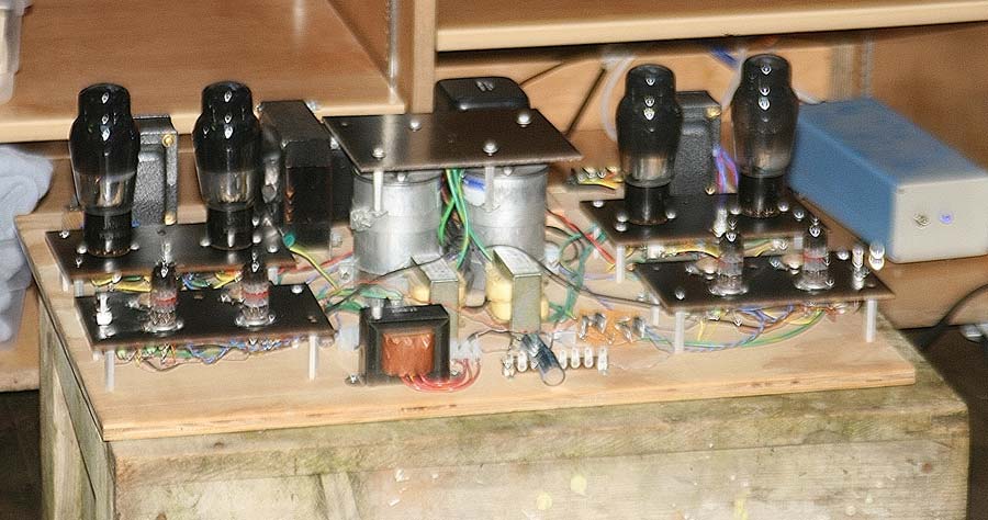
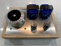
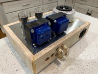
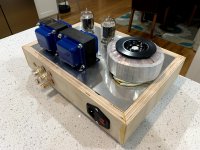
I finish the project on paper and assembling all components, this became also more complex because I add to the Berglund design a led display for every single frequencies so when finish I will have the exact idea of the equalisation.
I used 6N2P instead the 12AX7 but when finish I will replace with 6N2P-EV, also on the way, so I put all on a wooden board connect everything unfortunately with a not really good wire but is the only one available at the moment, so I was expected a not so good result or some not pleasant noise but with surprise when I put on the EQ all work very good and the sound is really amazing, no oscillation at all, just a little hum at the max vol of the amp, so I am extremely happy with the result so now looking forward to receive the missing component and cabinet for finalise this project, I still do not know how I will be able to do 100 perfect holes on the front panel of the cabinet but well will see.
The sound test was very good so next I will make some serious test with generator and scope and Rew, for the main time some pic of the EQ.
ah is a volumen monitor!
Thanks dude italiano
yes exactly, I didn't want ruin the original design so I decide to make a completely separate circuit for the display but at the same time able to display real signal level, so I design a specific circuit around the LM3914 and with the two trimmer 250k and 50k I am able to tune the display matching the EQ level...ciaooooo
This one both looks wonderful & sounds tremendous.
dave
Hammertone is such a nice finish for bell ends, (and everything else). Are those MQ-565 output tranformers?
Thanks so much!
Sure no problem here the schematic...all the best
It looks like a real tour de force build. Should be a looker once done.Here some pics of a stereo VT25A DRD amp.
some additional photos
Hello Bas,
Sure it take loads of time to get it done. Try to gather information how to get the wiring done right was the latest issue.
It looks like i know now how to get it done.
In the beginning the LCLCRC supply was done with all chokes having half of the wire so to say in the return. Peter van Willenswaard ( Audiomagic) told me not to do this for the second choke so i changed that.
All caps have their negative pole connected to the chassis at the same point from there will be a 35 cm wire running to the input tube.
The AC heater supply of the input tube will be guided along the opposite corner of the one that has the twisted black and blue from the Rod Coleman circuit running to the UX4 support. These wires are running close to the top plate and the 6,3 volt will be close to the bottom plate . Running it in parallel with the 35 cm mass wire would be bad.
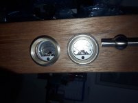
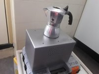
Have to finish the hole for the Yamamoto meters. Probably covering the inside with a black? plastic foil. It reminds me of the the Minions cartoon.
Greetings, Eduard
Hello Bas,
Sure it take loads of time to get it done. Try to gather information how to get the wiring done right was the latest issue.
It looks like i know now how to get it done.
In the beginning the LCLCRC supply was done with all chokes having half of the wire so to say in the return. Peter van Willenswaard ( Audiomagic) told me not to do this for the second choke so i changed that.
All caps have their negative pole connected to the chassis at the same point from there will be a 35 cm wire running to the input tube.
The AC heater supply of the input tube will be guided along the opposite corner of the one that has the twisted black and blue from the Rod Coleman circuit running to the UX4 support. These wires are running close to the top plate and the 6,3 volt will be close to the bottom plate . Running it in parallel with the 35 cm mass wire would be bad.
Have to finish the hole for the Yamamoto meters. Probably covering the inside with a black? plastic foil. It reminds me of the the Minions cartoon.
Greetings, Eduard
Attachments

update on capacitor mounting
Hello Bas,
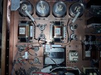
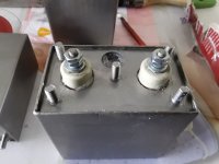
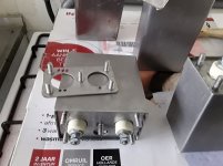
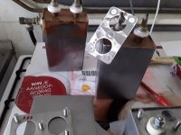
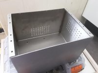
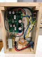
Yes, i made some stainless steel plate that fitted exactly into the small chamber of the CSI and the Russian oil capacitors.
The fixation bolts are 6 mm so you are tempted to attach them to powerfull!!. The plates were a little thinner than the space inside the capacitor so the outer rim of the cap will be on the top plate of the chassis and if you use to much power you the glued plate will come loose. I used some kind of elastic glue and it wasnt the best one for this purpose so i glued the CSI one more time using two component epoxy glue that is used at the company to glue alumium to an already powdercoated chassis. The '' designers '' have done some test to find the best glue. Dont know the brandname. I was only told how to use it. Degrease it!! Once the two parts are together you can slide them but if you seperate them the glue will NEVER work.
The Russian caps still glued with the not so powerfull elastic glue but i used some rubber rings to prevent to much force on the mounting glue.. When i put the chassis upside down it will be supported only by the highest and heaviest part ( 11,5 kilogram) which is the power transformer and input choke. When put on one of the sides it is also supported by this cover.
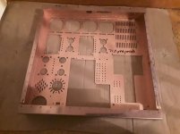
I had the two copper plate parts folded twice at each side AND added a small piece of aluminium in each corner to make it more ridged because the wooden frame doesnt add much strength.
Especially the power supply part have loads of holes so i needed to regain strength by the stainless steel covers on the top side. In the end that worked well.
When the chassis will not be sturdy it could be that soldering connection involving ridgid cable could be stressed during transport.
Greetings, Eduard
Hello Bas,
Yes, i made some stainless steel plate that fitted exactly into the small chamber of the CSI and the Russian oil capacitors.
The fixation bolts are 6 mm so you are tempted to attach them to powerfull!!. The plates were a little thinner than the space inside the capacitor so the outer rim of the cap will be on the top plate of the chassis and if you use to much power you the glued plate will come loose. I used some kind of elastic glue and it wasnt the best one for this purpose so i glued the CSI one more time using two component epoxy glue that is used at the company to glue alumium to an already powdercoated chassis. The '' designers '' have done some test to find the best glue. Dont know the brandname. I was only told how to use it. Degrease it!! Once the two parts are together you can slide them but if you seperate them the glue will NEVER work.
The Russian caps still glued with the not so powerfull elastic glue but i used some rubber rings to prevent to much force on the mounting glue.. When i put the chassis upside down it will be supported only by the highest and heaviest part ( 11,5 kilogram) which is the power transformer and input choke. When put on one of the sides it is also supported by this cover.
I had the two copper plate parts folded twice at each side AND added a small piece of aluminium in each corner to make it more ridged because the wooden frame doesnt add much strength.
Especially the power supply part have loads of holes so i needed to regain strength by the stainless steel covers on the top side. In the end that worked well.
When the chassis will not be sturdy it could be that soldering connection involving ridgid cable could be stressed during transport.
Greetings, Eduard
Attachments
6B4G
6.3V filament, Octal socket, 25V higher plate rating, otherwise 2A3 specs.
Thanks!
Found the maps:
dave
Hello,
I see the 0 of the output transformer connected to the earth, my output transformer also has a static screen. Static screen could be attached to the chassis like one usually does with the screen of a power transformer using one of the mounting screws of the transformer?
What about the 0 on the secundairy side connect it to the black loudspeaker terminal and from there a wire to the chassis or a certain location of the '' earth area'' ?
greetings, Eduard
A lot of metal fab. going on there.Hello Bas,
Yes, i made some stainless steel plate that fitted exactly into the small chamber of the CSI and the Russian oil capacitors.
The fixation bolts are 6 mm so you are tempted to attach them to powerfull!!. The plates were a little thinner than the space inside the capacitor so the outer rim of the cap will be on the top plate of the chassis and if you use to much power you the glued plate will come loose. I used some kind of elastic glue and it wasnt the best one for this purpose so i glued the CSI one more time using two component epoxy glue that is used at the company to glue alumium to an already powdercoated chassis. The '' designers '' have done some test to find the best glue. Dont know the brandname. I was only told how to use it. Degrease it!! Once the two parts are together you can slide them but if you seperate them the glue will NEVER work.
The Russian caps still glued with the not so powerfull elastic glue but i used some rubber rings to prevent to much force on the mounting glue.. When i put the chassis upside down it will be supported only by the highest and heaviest part ( 11,5 kilogram) which is the power transformer and input choke. When put on one of the sides it is also supported by this cover.
I had the two copper plate parts folded twice at each side AND added a small piece of aluminium in each corner to make it more ridged because the wooden frame doesnt add much strength.
Especially the power supply part have loads of holes so i needed to regain strength by the stainless steel covers on the top side. In the end that worked well.
When the chassis will not be sturdy it could be that soldering connection involving ridgid cable could be stressed during transport.
Greetings, Eduard
Hello,
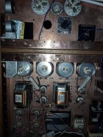
It is my job so it is rather easy to do with sometimes help of coworkers. Only the positioning of all the elements in two later connected copper chassis was a hard job. First made one in stainless steel to see if it has the looks.
I need to add some plastic foil inside the '' eye socket '' of the Yamamoto panel meters. They look like the Minions eyes. On each end of the wooden front panel there is a stainless steel T bar? This is not for really lifting the chassis but to pull it out of the audio rack so it can be really lifted by the two side panels.
Greetings, Eduard
Novar Spud by Tom Christiansen, AKA Neurochrome.
Nice one, congrats.
- Home
- Amplifiers
- Tubes / Valves
- Photo Gallery