
Beautiful! ...but what provisions have you made to prevent oxidation?
HiBeautiful! ...but what provisions have you made to prevent oxidation?
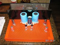
I cleaning the copper I sprayed 3 coats of Incralac using a 1.7mm nozzle waited 30+minutes between coats .
Incralac is a clear vanish designed for copper & copper alloy's .The surface fills like glass .There was no need to rub down between coats .
http://www.wattyl.com.au/library/TDS/Incralac.PDF
Cheers
Congratulations on a fine build with loctals! -One day I should try them; you're an inspiration!
I'd like to see a schematic- looks like LED bias- I'm curious what you did.
Having it be quiet counts for a LOT. Glad it worked out!
thanks, here it is, changed the leds to 3 string....
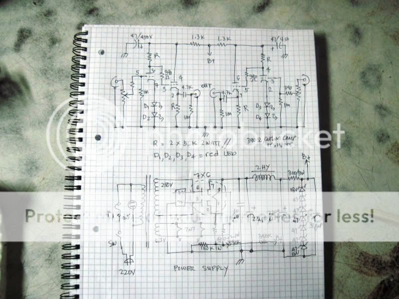
What is "L-W topology" ?Driver tube is EF860, output tube is 6C4C (6BG4).
L-W topology, output power 4 Watt.
Two independence inputs, load resistance 4 and 8 Ohm.
Is EF860 pentode or triode connected?
What is "L-W topology" ?
Is EF860 pentode or triode connected?
Other words it is Loftin-White schematic.
EF860 is pentode connected.
A voltage of the second grid is a steady-state by voltage regulator. I can regulate the plate current of output tube by this voltage regulator.
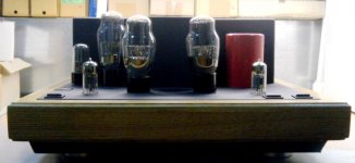
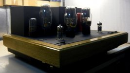
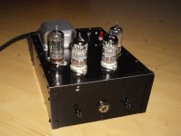
Here's an amplifier that I just finished. Its a 2V red LED biased 12sl7 split-load phase splitter, and a 6as7g garter-biased output stage. Power is from a toroidal isolation transformer with added heater windings.330V B+ (center tapped). The Input stage runs across the supply, the output stage gets a B+ of 165V from the PSU center tap. The output stage has a garter bias scheme, 330 ohms each resistor, with the cathodes connected through a 150uF non-polar electrolytic. 90V across each 6as7g, 30V across each R, and 10v lost in the transformer. Sounds very nice, and has very nice bass even with cheap speakers. Also pictured is my passive preamplifier, a basic 100k pot with basic RCA in/out, and a switching 1/8th input on the front.


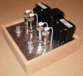
Very nice. I've been waiting for someone to use that tube-socket-on-PC-fan-guard trick. Did you see it in Morgan Jones too?
Yup, I like the different approaches to casing, I'm a little bored of the "wood box with a metal plate" approach to casing. Also, one Big hole is easier than a BUNCH of little ones.
Hi,
this is my first posting in this forum. What I am showing here is "work in progress": a triode headphone amp based on Kurt Strain's design ( HeadWize - Project: An OTL Tube Headphone Amplifier by Kurt Strain ). I made the enclosure from 1/16'' aluminum sheet. Due to an issue with hum I will relocate the power supply to a separate enclosure.
Warm regards,
Fred
Attachments
My latest creation. Class A, 3W per channel, single ended. Can be easily changed to pentode mode. I made this one for sale, but still not sold ") More info here: Forums - SE84C+ Review Tone Audio Magazine
More info here: Forums - SE84C+ Review Tone Audio Magazine
More info here: Forums - SE84C+ Review Tone Audio MagazineAn externally hosted image should be here but it was not working when we last tested it.
An externally hosted image should be here but it was not working when we last tested it.
An externally hosted image should be here but it was not working when we last tested it.
Hi,
this is my first posting in this forum. What I am showing here is "work in progress": a triode headphone amp based on Kurt Strain's design ( HeadWize - Project: An OTL Tube Headphone Amplifier by Kurt Strain ). I made the enclosure from 1/16'' aluminum sheet. Due to an issue with hum I will relocate the power supply to a separate enclosure.
Warm regards,
Fred
What about a look innside the amplifier?
Clean, very elegant. Good proportions. I like it.
Thank you. I am professional.
Empty space on front part of chassis looks odd, but there I will hide digital controls of inputs and volume. 5 inputs remote controlled (relays), and motorized fader remotely controlled, that controls relays of ladder attenuator.
Curious to see your regulator. I am trying to make a regulator that is not the maida, but there are not many design for power amps.
It is very simple: string of 2 Zeners, 120V each, in series, and couple of MOSFET followers, for 115 and 235V. Time constant for 15 S. Similar regulator for -40V, with very short time constant, and one for 6.3V using one MOSFET and one small BJT, with couple of LEDs for reference voltage. Excess 2.1V for 4P1L dropped by pair of 3 Ohm resistors per tube, one from each side. CTs of 4P1L filaments grounded. 6J5P and 6N16B filaments powered from regulated 6.3V.
Last edited:
Would never of thought of it but a good idea.Very nice. I've been waiting for someone to use that tube-socket-on-PC-fan-guard trick. Did you see it in Morgan Jones too?
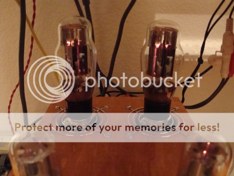
Any noise from the leds. They are meant to be noisy little devils.
Do we have postable schematic. I did a 12AX7/6AS7 SET. Just two tubes and rec tube. Love the amp-3W. Every one who listens to it wants one.
Now that's nice. I have an 807 amp to build with top caps. A way off yet.Mindutis: Nice amp, simple clean lines. I have a lot to learn.....
Just started the oak frame for the 2nd compactron amp.
Love the finish.Forgive my ignorance, I would like to ask what exactly is "engine turned" I really like it, wow!
- Home
- Amplifiers
- Tubes / Valves
- Photo Gallery